At an old job I programmed and ran both a CNC laser and CNC brake. We did a variety of jobs from onesie-twosies to 10k runs.
For the one-off stuff (like yours) I'd get handed everything from a napkin sketch or cardboard cutout and no cut file to insanely over dimensioned drawings I could hardly read to go along with the DXF. What I liked best was a clean DXF with bend lines, and a drawing with minimal dimensions but very clear callouts for each bend. If there was an odd line in the DXF I could quickly see on the drawing if it was a bend, or a slot, or just a glitch in the matrix. It's mandatory to include the orientation of the bend, and it's nice to know the length as well. If you have notches or etching from cutting then you don't really need to call out distance from the edge to the bend; it can really clutter up the drawing when you start stacking bends on bends on bends.
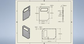
Halcyon's drawings look good (Except there's no explicit bend up/down orientation! Fortunately he included the ISO view, so I can interpret they're all bent down relative to that detail view) but if you print that on 8.5x11 those numbers are gonna get hard to read at a glance. If I was going to be bending that part I'd just grab the important stuff (circled in red) and print it 2x the size, that way I can tape the drawing to the front of the machine and see everything I need as I'm setting up.