What's new
What's new

Biax 7EL assembly/repair

RC99

Diamond
Joined
Mar 26, 2005
Location
near Rockhampton, Queensland, Australia
Biax 7EL assembly/repair (warning pic heavy)

I recently purchased a Biax 7EL scraper off ebay... The motor in it has problems which I knew about before I purchased and while I am getting them sorted out I decided to disassemble the mechanism and give it a clean and re-grease, while doing this I took note of the bearing numbers and also took photo's as I know a few members here have these machines and may need the info in the future....

Now the pictures are going to look a bit strange as I took them as I was putting it back together, but anyway here goes.

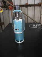
Firstly remove the motor assembly from the mechanical assembly by unscrewing the chromed ring.. It will end up looking like this

biaxpictures036.jpg


Then remove the hexagonal end cap and the tool holder (the tool holder screws are very tight, do not strip the heads, use the correct screwdriver), then remove the three small nuts, including the one that holds the leather strap on, the rear nut is shown in this picture.

You will end up with two pieces like so

biaxpictures035.jpg


biaxpictures032.jpg


Now remove the cotter pin on the stroke adjusting nut, remove the nut and screw out the adjusting bolt, then remove the three small screws on top of the stroke motion maker..Carefully prise out the top section so it looks like this

biaxpictures030.jpg
 
Clean up the stroke making thingie (technical term) The bearing in it is a double row deep groove ball bearing (bearing number 2200) and can be dissasembled to look like thus, there is a threaded retaining ring holding the bearing in...You will need to make a tool up to unscrew it..

biaxpictures007.jpg


biaxpictures005.jpg


Now we can unscrew the next piece from the shaft... You will notice two holes 180 degrees apart in the tool... You can insert some wire in there to lock the tool..

Picture of the holes

biaxpictures029.jpg


Now unscrew the other half of the stroke thingie like thus

biaxpictures025.jpg
 
I should point out all threads I came across were normal right hand threads..

Now there are two small nuts you can get to.... Unscrew these nuts and you can remove the gearbox casting cover

biaxpictures022.jpg


The bearings in here are as follows...

The bearing next to the steel helical gear is a deep groove ball bearing number 6201.

The bearing next to the stroke thingie is a double row angular contact bearing number 3203.

The steel gear and shaft comes out as an assembly..

biaxpictures019.jpg


The angular contact bearing can be removed by making up another tool to unscrew the retainer ..There is a belleville washer in here below the threaded retainer

biaxpictures018.jpg


You can now clean up all the components and check for wear..As far as I am aware no parts for this scraper are available anymore including simple items like brushes....

Assembly is a reversal of the description..
 
It has been bought to my attention the photo's are all gone...

I deleted my photobucket account as I was sick of all the bullshit photobucket was carrying on with with their "enhanced" website..

I still have the pictures so have uploaded them to the PM server..

So here is a redo....

I recently purchased a Biax 7EL scraper off ebay... The motor in it has problems which I knew about before I purchased and while I am getting them sorted out I decided to disassemble the mechanism and give it a clean and re-grease, while doing this I took note of the bearing numbers and also took photo's as I know a few members here have these machines and may need the info in the future....

Now the pictures are going to look a bit strange as I took them as I was putting it back together, but anyway here goes.

Firstly remove the motor assembly from the mechanical assembly by unscrewing the chromed ring.. It will end up looking like this

biax pictures 036.JPG

Then remove the hexagonal end cap and the tool holder (the tool holder screws are very tight, do not strip the heads, use the correct screwdriver), then remove the three small nuts, including the one that holds the leather strap on, the rear nut is shown in this picture.

You will end up with two pieces like so

biax pictures 032.JPG

biax pictures 035.JPG

Now remove the cotter pin on the stroke adjusting nut, remove the nut and screw out the adjusting bolt, then remove the three small screws on top of the stroke motion maker..Carefully prise out the top section so it looks like this

biax pictures 030.JPG
 
Clean up the stroke making thingie (technical term) The bearing in it is a double row deep groove ball bearing (bearing number 2200) and can be dissasembled to look like thus, there is a threaded retaining ring holding the bearing in...You will need to make a tool up to unscrew it..

biax pictures 007.JPG

biax pictures 005.JPG

Now we can unscrew the next piece from the shaft... You will notice two holes 180 degrees apart in the tool... You can insert some wire in there to lock the tool..

Picture of the holes

biax pictures 029.JPG

Now unscrew the other half of the stroke thingie like thus

biax pictures 025.JPG
 
I should point out all threads I came across were normal right hand threads..

Now there are two small nuts you can get to.... Unscrew these nuts and you can remove the gearbox casting cover

biax pictures 022.jpg

The bearings in here are as follows...

The bearing next to the steel helical gear is a deep groove ball bearing number 6201.

The bearing next to the stroke thingie is a double row angular contact bearing number 3203.

The steel gear and shaft comes out as an assembly..


biax pictures 019.JPG

The angular contact bearing can be removed by making up another tool to unscrew the retainer ..There is a belleville washer in here below the threaded retainer


biax pictures 018.JPG

You can now clean up all the components and check for wear..As far as I am aware no parts for this scraper are available anymore including simple items like brushes....

Assembly is a reversal of the description..
 
Thanks for reposting the pictures

FYI if anyone runs across one needing new brushes you can buy replacement brushes for a different motor and modify them to fit using a file.
 
First of all, I'd like to thank RC99 for having reposted the pictures of the Biax disassembly...I dug up this thread in the hope of understanding just how the bloody thing works, i.e how it generates alternating, adjustable linear motion from a rotary source. I tried searchin on the web for similar designs, but alas, I haven't found much. Not that I want to homebrew some similarly functioning contraption, not right now (much as the rarity and cost of Biaxes bug me no end). I just can't wrap my head around the mechanism that makes the stroke possible, what the hell is it? A modified crank? A swashplate?
 
That's why BIAX continues to re-up the Patent. They make a change after 7 years. You can contact Ed Dyjak he is a DAPRA distributor and has some parts for those old ones. His email address is: ESD2@aolcom He is a BIAX repair station and sells many things used in rebuilding. Rich
 
Richard,

thanks for the information, but what I was looking for was a "simple" explanation of how the thing works, i.e. what kind of basic mechanism transforms rotary motion into linear motion. It has to be some kind of already described mechanism, as I said above: a crank, a swashplate (which kind gets my vote), or a modification thereof.
 
First of all, I'd like to thank RC99 for having reposted the pictures of the Biax disassembly...I dug up this thread in the hope of understanding just how the bloody thing works, i.e how it generates alternating, adjustable linear motion from a rotary source. I tried searchin on the web for similar designs, but alas, I haven't found much. Not that I want to homebrew some similarly functioning contraption, not right now (much as the rarity and cost of Biaxes bug me no end). I just can't wrap my head around the mechanism that makes the stroke possible, what the hell is it? A modified crank? A swashplate?

It's hard to describe in words you'd have to take a look in person to see how simple yet clever a design it is - that will last a long time. I wouldn't fancy trying to copy it, better to go along the lines of the modified recip-saw that's been done a few times.

My own model, same as RC99's, had a couple of minor problems when I got it. The fan had become loose on the shaft which was fixed with a drop of PU glue and it would slow down when it got warm by binding the bearings if you had the locking ring done up tight, fixed with a thin gasket between the mating faces (and in fact it has cured itself of that with use).
 
Peter,

it's the "simple yet clever" thing that bites me. I have been trying to imagine some sort of modified swashplate along the lines of a hydraulic pump, but my mental design ends up being too fragile. Damn! :D
 
It's really simple , there is a bent shaft that rotates on it's own axis, now if you put a block on the bent end and rotate the shaft while keeping the block from turning you'll see the motion, rotary to linear.
 
Ok I'll have a stab at it.

The drum with the holes in it houses a swash plate that you can adjust the pivot angle to set the throw. An arm connects to the top of the swash plate via a bearing so that it's free to swing and the arm has a crank on it with a protruding pin set down at the same height as the pivot arms on the swash plate. Spinning the drum whilst restraining the rotation of the arm causes the arm to nod producing a reciprocating motion at the pin, which also rotates through a small arc each turn.
 
Richard,

thanks for the information, but what I was looking for was a "simple" explanation of how the thing works, i.e. what kind of basic mechanism transforms rotary motion into linear motion. It has to be some kind of already described mechanism, as I said above: a crank, a swashplate (which kind gets my vote), or a modification thereof.

I wasn't directing what I said to you.... was general info like J R wrote.
 
@Peter:

thanks for your efforts, your description steered me into the right direction.
To top it off, I discovered I ought to do my homework better:

www.practicalmachinist.com/vb/gener...onvert-makita-hk0500-metal-161099/index5.html

Here's a direct link to one of the patents. The drawings and cut-aways explain in great detail how the swashplate/wobble plate/Taumelgetriebe (german) works.

Patent US2940324 - Wobble drive - Google Patents

Not exceedingly difficult to replicate if one knows his way around a lathe and a milling machine, IMHO.

Mauro
 
Many thanks, RC. Takes out the guesswork and gives me confidence that I've removed all necessary fasteners before I pull hard on things. Also, a benefit to taking the pictures as you reassemble it is that all of the previous gunk has been removed. I think I got 1-2 fluid ounces of old grease out of mine...

FWIW, on mine, the big, four-point castellated nut thingy (not the little castellated hex bolt) is made of brass. Serial number L/3202/74


Back
Top