What's new
What's new

Blunt Start Thread (Higbee) Questions

maguilera

Aluminum
Joined
Jan 4, 2022
First and foremost, before posting here I did some research on this topic and read through a few threads on PM and they were really helpful, but still, some questions arose.

Is it an issue to use a LH tool to cut the higbee on a right hand thread?

The Z start position of the higbee should be kept the same as the threading? Or should it be displaced by the pitch or half the pitch?

Is it possible to cut a higbee using a WNMG or TNMG insert?

I believe I could get an answer for these questions by loading the program and running some test pieces, but I don't have a machine available for doing that at the present moment.

This is the program I came up using G76 for an M30x2 thread, assuming the preset is at the center tip for the threading tool and at the leading edge for the grooving tool.

(M30x2 THREAD – REAR TURRET LATHE)

T0505 (RH OD THREADING TOOL MOUNTED UPSIDE DOWN)

G97 S800 M3

G0 G54 X38 Z6

G76 P010060 Q100 R0.1

G76 X27.546 Z-22 P1340 Q420 F2

G53 G0 X350 Z440

(HIGBEE)

T0303 (3mm LH OD GROOVING TOOL)

G97 S800 M4

G0 G54 X38 Z6

G76 P010060 Q100 R0.1

G76 X27.546 Z-2 P1340 Q800 F2

G53 G0 X350 Z440

Your input is greatly appreciated.

Cheers.
 
Is it an issue to use a LH tool to cut the higbee on a right hand thread?
No, but the front of the Tool Holder is going to be closer to the chuck, or shoulder on the Threaded part, if there is a shoulder or other feature that the tool may interfere with. There is really no advantage in using a LH Tool and negatives for using it.

The Z start position of the higbee should be kept the same as the threading? Or should it be displaced by the pitch or half the pitch?
Half the Pitch.

Is it possible to cut a higbee using a WNMG or TNMG insert?
Yes, but you would probably have to make multiple passes with slightly shifted Z Start Points.

The grooving tool would work starting at Z6.0, given its width of 3.0mm. Z5.5 would put the crest of the Thread in the centre of the Grooving insert, but this would cause the leading edge of the insert to interfere with the flank of the thread at its root.
You really should be using a Grooving Insert that is narrower than 3mm, or with the tool Offset in Z so that the leading edge of the insert is only 1mm forward of the centre line of the Thread Crest. More than that will have the leading edge of the insert interfering with the thread forward of it at its root.

It's not such a good idea to set the Offset of the Threading Tool at the centre of the Thread Form in Z. It's much more common and accepted, to program the Leading Edge of the Threading Tool/Threading Insert, so that you know exactly where the Leading Edge is during the Threading Operation. If there is a shoulder at say, Z-20.0 and you need to thread as close as possible to the shoulder, the programmed Z Coordinate could be Z-19.05 and you would know that the tool won't hit the part feature. Using the centre line of the Thread Form of the Insert would require you to accurately measure the distance from the leading edge of the tool to the Insert Centre line and calculate a Z Coordinate to use in the program. Best use the Leading Edge of the Tool and be done.

Regards,

Bill
 
Last edited:
Firstly, thanks for the explanation Bill.
Yes, but you would probably have to make multiple passes with slightly shifted Z Start Points.
So in this case I’d need to use G32, correct? How would I go about calculating the shift in Z for this case?

Cheers.
 
Firstly, thanks for the explanation Bill.

So in this case I’d need to use G32, correct? How would I go about calculating the shift in Z for this case?

Cheers.
The bigger the TNR, the bigger each Z Offset can be. You would need as many passes that equates to the thickness of the Thread Form at its root (in practical terms it will be close to the pitch), divided by the Offset of the tool in Z for each pass. The amount of variation in Z for each pass will depend on the finish you want on the Higbee surface of the Thread Form. If you were to move a 0.8 TNR tool in 0.25mm steps in Z, the finish would be the same as a turned surface using a Feed Rate of 0.25 per rev. Using G32, you could index the start of each pass using a Q address. To index the start to equate to a 0.25 axial shift, the angle would be 45 degrees indexed 8 times.

Regards,

Bill
 
Oh, this is lathe. I often Higbee threadmilled external threads, and just use a small diameter endmill following a partial helix pulled from the model.
 
The bigger the TNR, the bigger each Z Offset can be. You would need as many passes that equates to the thickness of the Thread Form at its root (in practical terms it will be close to the pitch), divided by the Offset of the tool in Z for each pass. The amount of variation in Z for each pass will depend on the finish you want on the Higbee surface of the Thread Form. If you were to move a 0.8 TNR tool in 0.25mm steps in Z, the finish would be the same as a turned surface using a Feed Rate of 0.25 per rev. Using G32, you could index the start of each pass using a Q address. To index the start to equate to a 0.25 axial shift, the angle would be 45 degrees indexed 8 times.
Thanks again for the detailed explanation.

So in this case, for cutting the higbee using G76 cycle with a TNMG insert, I’d need to call the G76 cycle 8 times, with the first threading pass depth the same as height of thread (all other parameters remains the same), but shifting the Z start position by 0.25mm each time. Is that correct?

Cheers.
 
Thread and Higbee on 0TC. Just finished 155 parts. Notice the greatly reduced spindle speed for Higbee.


N810 T0505(4 PITCH ACME OD)
N820 M41
N830 G97 S300 M3
N840 G0 X2.79 Z7.375
N850 M8
N870 G76 P000029 Q0 R0
N880 G76 X2.48 Z6.3 P1350 Q200 F.25
N890 T0500 M09
N900 G0 X11.7312 Z13.0
N910 M01

N920 T0606(.25 TOP NOTCH GROOVE)
N930 M41
N940 G97 S60 M3
N950 G0 X2.79 Z7.375
N960 M8
N980 G76 P000029 Q0 R0
N990 G76 X2.48 Z6.875 P1350 Q100 F.25
N1000 T0600 M09
N1010 M05
N1020 G0 X11.7312 Z13.0
N1030 M30
 
Notice the greatly reduced spindle speed for Higbee.
Hello alphonso,
I see that the Z Start for both the Threading and Grooving tool is the same. All things being equal, that shouldn't have worked. However, changing the Spindle Speed when screw cutting will index the Thread Start. For example, if you were to halve or double the Spindle Revs and execute an identical Threading Cycle twice on the one part, a Two Start thread will be cut.

The fact that the Revs for the Higbee operation is 1/5th of the Threading Revs would have done the trick. Either this was by design, or you got lucky.

Regards,

Bill
 
Thanks again for the detailed explanation.

So in this case, for cutting the higbee using G76 cycle with a TNMG insert, I’d need to call the G76 cycle 8 times, with the first threading pass depth the same as height of thread (all other parameters remains the same), but shifting the Z start position by 0.25mm each time. Is that correct?

Cheers.
Yes. that's correct.
 
Bill,

Sort of by design and fumbling around. The relatively slow rapids on this machine made slowing spindle to be the easier way to get the tool out of the thread. Still was about a quarter way round before tool cleared thread. Long Higbee. :D:D Customer is happy with parts.
 
I tried this on just a thread I made up. I run it on a GE Mark Centry 2000 just as a test about ten years ago. A discussion here prompted me to give it a whorl. I jacked around with it a couple times and this was about the best pull out I could get. To get it to come out looking like a fire hose fitting you about need to mill it. The object is a thread that won't cross thread and I believe this wouldn't?

Brent

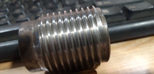
20191203_003030.jpg20191203_002929.jpg
 
I tried this on just a thread I made up. I run it on a GE Mark Centry 2000 just as a test about ten years ago. A discussion here prompted me to give it a whorl. I jacked around with it a couple times and this was about the best pull out I could get. To get it to come out looking like a fire hose fitting you about need to mill it. The object is a thread that won't cross thread and I believe this wouldn't?

Brent

View attachment 383384View attachment 383385
That's as good a Higbee as I've seen using a groove tool. I was told long ago that the main reason was to get rid of the sharp, imperfect thread at the start. It minimized parts not fitting due to damage when handled roughly in oilfield usage.
 
That's as good a Higbee as I've seen using a groove tool. I was told long ago that the main reason was to get rid of the sharp, imperfect thread at the start. It minimized parts not fitting due to damage when handled roughly in oilfield usage.

Came from fire hoses, I'm pretty sure. I did some nozzles once, the guy went into it at great length. And yardbird is right, you'll never get a real higbee on a normal lathe (can with live tooling I guess). It's got to be milled.
 
I've seen them on both fire fighting equipment and downhole drilling equipment. In both applications I've seen milled and turned versions. Higbee and blunt start seemed to be used interchangeably in the places I have seen making them.
 
Wasn't the kick out on Dean, Smith & Grace lathes specifically for Higbee?

Really ? Never had one of those. G&L made some nifty threading stuff (cnc) for wire rope spools tho. Remember that way that if the wire goes around straight then kicks, then goes around straight then kicks, can get more rope on a spool than a normal helix ? G&L had a way to do that. And some special pickup-the-thread repair cycles too.

I just saw them, never had one, too big even for me but looked cool.
 
Hello alphonso,
I see that the Z Start for both the Threading and Grooving tool is the same. All things being equal, that shouldn't have worked. However, changing the Spindle Speed when screw cutting will index the Thread Start. For example, if you were to halve or double the Spindle Revs and execute an identical Threading Cycle twice on the one part, a Two Start thread will be cut.

The fact that the Revs for the Higbee operation is 1/5th of the Threading Revs would have done the trick. Either this was by design, or you got lucky.

Regards,

Bill
We run higbees on Acme and Stub Acme all day every day. Almost every part has at least one on it. I estimate start point ( in the program ) then we edit to make it right. Some shops here do what Alphonso did then just offset the tool to get it right. ( which I despise and dont allow here) With a little practice its easy to get them right very quickly.

Also, some shops set z offset on the face of the thread tool, some on the tip. Obviously this affects where the thread actually is. The difference between a TNMC 43 and 54 affect where the thread is if setting on the face of the insert
 
I estimate start point ( in the program ) then we edit to make it right.
It's not rocket science to calculate the start point to get it right first time. Alphonso may have got it close just by the fact that the Z Start Point is the same for both the Threading Tool and the Grooving tool if each were set in Z for the leading edge of the tool. Given that the centre line of the Thread Form is back from the leading edge of the tool, that may have been close to the correct offset. But he also varied the spindle revs, which would have indexed the Z Start Point
Some shops here do what Alphonso did then just offset the tool to get it right. ( which I despise and dont allow here)
Isn't that what you said you do?
I estimate start point ( in the program ) then we edit to make it right.
 
It's not rocket science to calculate the start point to get it right first time. Alphonso may have got it close just by the fact that the Z Start Point is the same for both the Threading Tool and the Grooving tool if each were set in Z for the leading edge of the tool. Given that the centre line of the Thread Form is back from the leading edge of the tool, that may have been close to the correct offset. But he also varied the spindle revs, which would have indexed the Z Start Point

Isn't that what you said you do?


We edit the program vs offset the tool ( edit code vs use geometry or wear offsets )
 
We edit the program vs offset the tool ( edit code vs use geometry or wear offsets )
Apart from change the spindle in spindle revs, which would index the Z Start, I can't see where alphonso has done what you're suggesting he has, perhaps you can point that out where he has.

As I've stated in earlier Posts, the safest and fairly universally accepted methods of setting a Threading Tool in Z is to use the leading edge of the Insert as the reference. Given that the centre line of the Thread Form of the Threading insert is an amount back from the Leading Edge and it would be dumb not to set Leading Edge of a grooving tool to be used to cut the Higbee, there is more than a fair chance that Start in Z for the Grooving Tool will correct, relative to the actual position of the Thread Form of the Threading tool.

Further, I don't think there has been any mention, apart from your own, of using Tool Offsets to adjust the Z Start position of the Grooving Tool.

If a change in Spindle Speed were to be used to index the start position of the Grooving Tool, that is editing the program and not the Tool Offset. If G32, G92, or FS15 Standard (single line Multi-repetitive Cycles) G76 cycles used, then the Start for the Higbee could be made with a Q address, which is easily calculated and made in the program.


Back
Top