AgentStone
Plastic
- Joined
- Oct 19, 2021
Greetings!
So... I am getting this old Mori SL25 Lathe going for a friend and was wondering a few things right off the bat.
1.How do I find the center of the spindle (and tell the machine that) for the X value in the work coordinates?
2. What is the best strategy for setting tools by hand since the tool setter is broken?
3. Last, what is the most intelligent way to set my Z work offsets once the tools are set?
Maybe I do 2 and 3 in reverse?
Thanks for any tips!
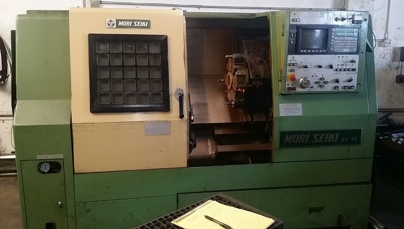
It looks just like this SL-15 below
So... I am getting this old Mori SL25 Lathe going for a friend and was wondering a few things right off the bat.
1.How do I find the center of the spindle (and tell the machine that) for the X value in the work coordinates?
2. What is the best strategy for setting tools by hand since the tool setter is broken?
3. Last, what is the most intelligent way to set my Z work offsets once the tools are set?
Maybe I do 2 and 3 in reverse?
Thanks for any tips!
It looks just like this SL-15 below