What's new
What's new

Brother S1000 4th Setup

Pete Deal

Stainless
Joined
Apr 10, 2007
Location
Morgantown, WV
Brother S1000 4th Axis Setup

I bought a new Brother S1000 about a year and a half ago. I got the Brother T200 4th axis with it. When they installed the machine the tech set the 4th up but I removed it from the machine soon after. I didn't have time to get into tooling at that point and figured it would be one less thing in the way till I had the time to mess with it.

Last week was the time. I never saw anything off the shelf that looked like what I wanted so I ordered some ductile iron from McMaster and made a faceplate and tomb stone. The T200 doesn't come with any faceplate at all. It just has the raw hollow shaft looking at you when you get it. It's tight in Z but workable for my needs. At least I think it is, haven't actually used it yet. To mount the T200 rotary table on the S1000 an adapter plate is required. This adds about 3/4" of unwanted height. Getting rid of this adapter plate is on the list of stuff to do. Also shortening up my Haimer probe will help. The tomb stone as is will allow a vise to be mounted on either side. Also, the vise I ordered has the SMW mounting pattern This allows the vise to be mounted in the two directions shown on a 4" wide tomb stone. I may in the future as needed make it so the tomb stone can be mounted lower on the face plate if I need even more Z.

Getting the dowel pin holes located precisely was a worry. A few years ago I cobbled a 30 taper kaiser boring head setup together off ebay but never used it. It's an EWN2-32. I really didn't know much of anything about these. I learned that getting the boring head is just the start. Man are they proud of the pieces. And although it's supposed to handle holes between 2-32mm by the time you bought the parts for it do do that you'd have a pile of money in the setup. I wound up adapting a 5/16" carbide bar I have to it and man does that thing work nicely! Much better than my past experience with my chicom Criterion copy.

Not shown but I still have enough room for two 6" vises too.

This is my first time at any 4th axis work. Now I've been reading about the center of rotation programming for this control. I found out yesterday that the G54.2 is an option I don't have. So one question I have is how useful is this for 4th axis work? For now it will all be positioning. It seems it would be a very nice option since only one work offset would need to be set on the part. Also it seems like it ought to be much more accurate. It can be added for about $1000 but how helpful is it?
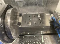

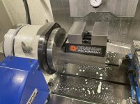
IMG_2715.jpgIMG_2716.jpgIMG_2717.jpg
 
Last edited:
Nice setup! I don't program from COR. Every index is it's own WCS.
I have a macro that if you input the first WCS, it will calculate a new WCS at whatever angle you tell it.

ie: I probe G54 XYZ A0, the macro will calc. G55 XYZ A90, G56 XYZ A-90, etc.
 
Nice setup! I don't program from COR. Every index is it's own WCS.
I have a macro that if you input the first WCS, it will calculate a new WCS at whatever angle you tell it.

ie: I probe G54 XYZ A0, the macro will calc. G55 XYZ A90, G56 XYZ A-90, etc.

I'm still just figuring this out but I guess somewhere you store your center of rotation coordinates? I think that needs to be known to solve for your new location right?

I guess I also could make a spread sheet to do this too. Can I get a copy of your macro?
 
Here's the macro. This is on a Haas.

%
O09010 (Work Shift Macro)
#900= -8.0498 (Center of rotation Y)
#901= -17.9212 (Center of rotation Z)
#903= #7341 (Read G127 X) (I use G127 as the initial probed WCS)
#902= #7342 (Read G127 Y)
#904= #7343 (Read G127 Z)
#905= #7344 (Read G127 A)
#911= #902 + #25 - #900 (adjust Y to account for center of rotation and add any shift amount)
#912= #903 + #24 (add any shift amount to X)
#913= #904 + #26 - #901 (adjust Z to account for center of rotation and add any shift amount)
#914= #905 + #1 (add any shift amount to A)
IF [ #911 EQ 0 ] #911= 0.000001
#915= SQRT[ #911 * #911 + #913 * #913 ]
#916= ATAN[ #913 / #911 ]
IF [ #911 LT 0 ] #910= #916 + 180 GOTO2
GOTO3
N2
#917= COS[ #1 + #910 ] * #915 + #900
#918= SIN[ #1 + #910 ] * #915 + #901
GOTO4
N3
IF [ #911 LE 0 ] #910= #916 + 360 GOTO2
N5
#917= COS[ #1 + #916 ] * #915 + #900
#918= SIN[ #1 + #916 ] * #915 + #901
N4
IF [ #23 EQ 1 ] GOTO6 (check W value)
IF [ #23 EQ 2 ] GOTO7
IF [ #23 EQ 3 ] GOTO8
IF [ #23 EQ 4 ] GOTO9
IF [ #23 EQ 5 ] GOTO10
IF [ #23 EQ 6 ] GOTO11
IF [ #23 EQ 7 ] GOTO12
IF [ #23 EQ 8 ] GOTO13
IF [ #23 EQ 9 ] GOTO14
IF [ #23 EQ 10 ] GOTO15
IF [ #23 EQ 11 ] GOTO16
IF [ #23 EQ 12 ] GOTO17


N6
#5221= #912 (Write G54 XYZA)
#5222= #917
#5223= #918
#5224= #914
GOTO18
N7
#5241= #912 (Write G55 XYZA)
#5242= #917
#5243= #918
#5244= #914
GOTO18
N8
#5261= #912 (Write G56 XYZA)
#5262= #917
#5263= #918
#5264= #914
GOTO18
N9
#5281= #912 (Write G57 XYZA)
#5282= #917
#5283= #918
#5284= #914
GOTO18
N10
#5301= #912 (Write G58 XYZA)
#5302= #917
#5303= #918
#5304= #914
GOTO18
N11
#5321= #912 (Write G59 XYZA)
#5322= #917
#5323= #918
#5324= #914
GOTO18
N12
#7001= #912 (Write G110 XYZA)
#7002= #917
#7003= #918
#7004= #914
GOTO18
N13
#7021= #912 (Write G111 XYZA)
#7022= #917
#7023= #918
#7024= #914
GOTO18
N14
#7041= #912 (Write G112 XYZA)
#7042= #917
#7043= #918
#7044= #914
GOTO18
N15
#7061= #912 (Write G113XYZA)
#7062= #917
#7063= #918
#7064= #914
GOTO18
N16
#7081= #912 (Write G114 XYZA)
#7082= #917
#7083= #918
#7084= #914
GOTO18
N17
#7101= #912 (Write G115 XYZA)
#7102= #917
#7103= #918
#7104= #914
GOTO18

N18
M99

%
This example is for a 3" round disc X 1" thick. The center of the disc is zero at G54 A0, the OD is Z0 at A90 and A-90

Call the macro:

G65 P9010 W1 X0 Y0 Z0 A0 (assign G54)
G65 P9010 W2 X0 Y1.5 Z0 A90. (Move new WCS to calculate up to the edge of the OD) (Shift Y up 1.5" assign to G55)
G65 P9010 W3 X0 Y-1.5 Z0 A-90. (Move new WCS to calculate down to the edge of the OD) (Shift Y down 1.5" assign to G56)


All shift amounts come from the initial orientation at A0.


Sounds confusing but not after you get used to it. I'll answer any questions if I can.
 
Last edited:
I saved it off and will sit and have a look at it. Maybe tonight while taking my daily booze! Thanks.

This seems like it may be a good way to go for me.
 
I program from center of rotation on all my rotary 4th axis. Even a fixture on the trunnion that holds 10 pieces are all just one fixture location.
I know back when I was doing stuff on my Fadal 15XT with 5C indexer we had to set each rotation as it's own fixture location to make sure things would blend well, but the brother is spot on.

PS, what is this G54.2 you speak of?
 
Basically you’re using the probed Y and Z compared to COR Y and S to make a right triangle. Calculate the angle and length of the hypotenuse, rotate thru the desired angle and back figure the new triangle.

Don’t booze too much. :D
 
That is a nice setup!

You are looking a little height challenged. I might redo the trunnion with the top of the vise closer to the COR. I find I use a vise on the 4th for very low-volume work, but anything I'll make in substantial numbers gets a quick-n-dirty fixture in aluminum, so the benefits of 2 vises outweighs the massive lack of Z and the inaccuracies that inherently come from hanging so far away from the COR.

Brother does have G54.2, but it works in a very funky way - you put the COR datum in a standard G-code slot (G54, G55, etc), while the part location goes into this funky position in the G54.2 menu. It is a pain because it is hard to send probe data to those locations, though I think Yamazen has developed some macros to solve it. Most other controls have you set COR up once in a buried menu, and then your part locations are in the standard G-code slots so it is just easier to input and tweak. The way Brother does it is for a mass scale factory floor where all your fixtures are basically dialed in, but you don't know precisely where the 4th axis platter is going to wind up across the fleet.

For large scale production gigs, we program off of the COR, but we replicate that offset for each index angle and sometimes even for critical features. So at the start, G54-G56 will all have the same offset, but different operations will call a different address. Our goal is to make everything as straightforward and easy to manage on the shop floor as possible. If a feature on the side of the part is of by Y+0.001, go to the work offset for that side and comp Y-.001 and it is solved. If we notice every offset is getting tweaked the same amount, it tells us we have a COR offset or even fixture alignment issue that needs to be addressed.

In the end, I don't think G54.2 would have a good ROI as I think it would add a lot of complexity but little benefit to our workflow.
 
Well, it does seem that Booze Daily's macro pretty much does the same thing. I still need to digest it but I think I generally understand what he's doing. I never programmed any macros so this is probably a good place to start.

Regarding the Z and vise use. This machine I pretty much use for contract work and the quantities so far don't get past a few hundred. I think it's hard to beat a vise for that. I had thought that I could add some fixture mounting capability to the tomb stone too if it's needed. For most of what I have going now, pretty small parts, I think the Z will be ok with a little effort. We'll see.

I also have a TC-S2DN-O that I have dedicated to my own production parts. It has a Yukiwa 4th axis and support table with it. Not using that yet either. That's next on the list. The Yukiwa table is not quite as tall as the Brother table. The S2DN had a column riser in it which I removed. I bought it used. I think it had been used to finish valve covers or something.
 
Just a side note...when I originally read the thread I thought this was only your 4th time setting up the machine in a year and a half...thought you guys might have a chuckle on me.
 
Brother does have G54.2, but it works in a very funky way - you put the COR datum in a standard G-code slot (G54, G55, etc), while the part location goes into this funky position in the G54.2 menu. It is a pain because it is hard to send probe data to those locations, though I think Yamazen has developed some macros to solve it. Most other controls have you set COR up once in a buried menu, and then your part locations are in the standard G-code slots so it is just easier to input and tweak.

In the end, I don't think G54.2 would have a good ROI as I think it would add a lot of complexity but little benefit to our workflow.

You can use any work offset G54-G59 or G54.1 P1-P48 to set COR. For a 4th (A-Axis) you’ll really only set Y and Z in there. Then the G54.2 Rotary Fixture Offset values will be the distance from desired WCS to COR in XYZ and compensation for A-Axis. All of the data population to the RFO table can be handled simply thru a G10 line.

The way I’ve gotten it to work with probing is to set G54.1 P47 to COR, then probe everything to G54.1 P46 for reference to handle the math. Once P46 is set the differences are subtracted and populated via macros into the G10 line and pushed into the RFO page. It’s extremely easy, and can be done via the standard probing cycles at the beginning of the calculation program, or can just run the calculation as a sub after you set P46. P46 is only used for the math.

The G10 line allows you to select which offset to use, G54.2 P1-P8, what values to populate, ABCXYZ, and which axis to compensate, in this case just A. The only missing link at this point is the post, which isn’t really very difficult, just needs G54.2 P1-P8 output after the COR WCS (G54.1 P47 in this case). Not a difficult edit. I have all this working on M Series Speedios as well as Tilting Rotaries and just straight Rotaries. It works really well.

The real question is, do you care what your code looks like? Do you want to model in your vise and COR every single time or just program the part and stick it wherever you want? Do you ever skim your jaws and if so do you really want to go back in CAM and move everything to match? I don’t, and I want my code to make sense off the part dimensions so G54.2 in my opinion is a worthwhile option, especially in a job shop environment.

If you’re only ever going to be working in a vise that’s never going to move in XYZ though, maybe going off of COR is an easy solution and essentially free. Really just depends on if the setup will change or not and if you care what the code looks like.


Below is a copy of the program I made and have been using with notes. The probing can be edited to whatever cycles you prefer, for this example it’s top center of stock. Can also add tool change info and prepositioning if done in production.

Edit: The three probing cycles below are Blum so if you’re using Renishaw, some changes will need to be made.

(ROTARY FIXTURE OFFSET)
(PROBING CENTER + TOP OF STOCK)
(POSITION PROBE .250 FROM Z FACE)
(POSITION PROBE XY CENTER OF STOCK)
(G54.1 P46 IS USED FOR CALCULATION)
(G54.1 P47 IS CENTER OF ROTATION)

(USER INPUTS)
#1=1 (REFERENCE ROTARY FIXTURE OFFSET NUMBER 1-8)
#8=0 (SET AXIS FOR CALCULATION - SEE NOTES)
#9=3. (OUTSIDE WIDTH IN X)
#10=2. (OUTSIDE WIDTH IN Y)

(CLEAR OUT REFERENCE ROTARY FIXTURE OFFETS BEFORE SETTING)
#2=0 (CLEAR X VARIABLE)
#3=0 (CLEAR Y VARIABLE)
#4=0 (CLEAR Z VARIABLE)
#5=0 (CLEAR A VARIABLE)
#6=0 (CLEAR B VARIABLE)
#7=0 (CLEAR C VARIABLE)

(PROBING CYCLES)
(SETS XYZ TO G54.1 P46 FOR CALCULATION ONLY)
G65 P8700 W-46. X1 Z-.5 S#9 (OUTSIDE WIDTH X)
G65 P8700 W-46. Y1 Z-.5 S#10 (OUTSIDE WIDTH Y)
G65 P8700 W-46. Z-0.25 (SINGLE TOUCH Z)

(CALCULATIONS)
#2=[#7901-#7921] (X CALCULATION)
#3=[#7902-#7922] (Y CALCULATION)
#4=[#7903-#7923] (Z CALCULATION)

(DATA INPUT FOR REFERENCE ROTARY FIXTURE OFFSET)
G90 (ABSOLUTE POSITIONING)
G10 L21 P#1 X#2 Y#3 Z#4 A#5 B#6 C#7 Q#8

M30


(NOTES)

(SYSTEM VARIABLES)
(REFERENCE WORK OFFSET FOR CALCULATION)
(G54.1 P46)
(#7901=X)
(#7902=Y)
(#7903=Z)
(#7904=A)
(#7905=B)
(#7906=C)

(CENTER OF ROTATION WORK OFFSET)
(G54.1 P47)
(#7921=X)
(#7922=Y)
(#7923=Z)
(#7924=A)
(#7925=B)
(#7926=C)

(ADDITIONAL REFERENCE)
(3.6.9 DATA INPUT FOR REFERENCE ROTARY FIXTURE OFFSET)
(COMMAND FORMAT G10 L21 PN X_ Y_ Z_ A_ B_ C_ QM; )
(N : REFERENCE ROTARY FIXTURE OFFSET NUMBER 1-8)
(X, Y AND Z : REFERENCE OFFSET)
(A, B AND C : REFERENCE ANGLE)
(Q : AXIS FOR CALCULATION)
(M = 0 : A-AXIS)
(M = 1 : B-AXIS)
(M = 2 : C-AXIS)
(M = 3 : AB-AXIS)
(M = 4 : AC-AXIS)
(M = 5 : BC-AXIS)
 
Last edited:
Thank you guys for all the good info! Couch, beautiful progamming, great commenting!

I need to start with macro programming 101. I never wrote any macros so I guess this is a great time to wade into these waters. Last night I sat with my programming manual and a glass of bourbon and studied Brother macros and the system variables. I won't muddy the waters of this thread with any macro programming questions.

Couch I don't have probing on my machine, my probe is a Haimer Taster. I think I generally have the idea of what I need to do.

Ultimately it seems like the macro can do what the G54.2 would do. Maybe for full 4 axis simultaneous the G54.2 would be more necessary but since I am only positioning for now really, as I am understanding, the macro accomplishes the same thing.

Sounds like it will! I haven’t read thru it in detail but quick glance it looks good!

G54.2 will work without probing, just need to input the values by manually measuring the difference between COR and your WCS. If you don’t have the option though, I’d give the macro a shot and see how it works out. Can always add the option later, the install is dead simple, just plug the chip in and unlock it with a password.

I have a long way to go with macros, just started messing with them this year but between Peter Smids FANUC Macro B book and the Speedio Programming Manual, you’ll get a solid handle on it. All the syntax/etc is the same as FANUC. Most System Variables as well.
 
This thread is relevant to my interests...

FWIW I talked to Martin Manufacturing about trunnion tables, and while their options in cast iron are very economically priced, they were just too high off the table for my liking. Especially because, as you are, I am going to hang the 4th off the table with a riser (mine is even taller at 40mm).

I've got a really low-slung table modeled up that will drop it so the flats on a Lang vise will be at COR of the 4th. I just need to find the time to make it.

I am actually considering making it out of 6061 instead of A36 or 4140PH. Price difference isn't much so I should probably just jump to the 4140PH.

I got a quote on the G54.2 option and it is around $1k if I recall, so not too bad. I don't mind programming COR, and I like the idea of having a WCS for each index location that are all still COR, but can be tweaked individually. I guess running full 5-axis stuff on FANUC just spoiled me and I want to be able to probe things in on an angle and cut them without mucking about too much in CAM.

If that macro looks promising to those who understand this stuff better I'll give that a try before dropping the money on the option, but ultimately it is probably in my future.
 
I can't get excited about aluminum for a fixture like this. My hope is that it will last a while with lots of removing/installing.

The ductile iron was relatively nice to work with. It machines nicely and doesn't seem to move. I'd say very close to 1018 but finishes nicer and more stable.

With mine as shown I can probably lower it by 2" by adding another bolt pattern to the face plate. I'd need to modify the design some though. I machined a 1.5" pocket in the center of the face plate and a mating boss on the trunnion table. I'd need to remove the boss and maybe add some locating pins. Maybe just bolt it and indicate it. Not gotten that far yet.

I think you have the T200 too right? Can't remember. Anyway, one thing I screwed up on the face plate is that the T200 table has two 8mm locating pin holes. I didn't pay careful enough attention to the drawing and assumed they were on the same diameter as the bolt circle. Not so. I have a boss on the face plate though that fits into the T200 spindle so it centers it very well.

Also, on the S1000 the table goes very close to the enclosure in X so there is no real table space saving advantage to moving the 4th off the table end as with the S700. So no real advantage to a baseplate for the 4th.
 
Yeah the 8mm dowels are also offset top and bottom.

I actually just cut the collar as a nice slip fit a few thousandths shallow into a Lang quick point plate. That way it was located pretty rigidly but stands proud of the T200 face and doesn't rub. I ended up shimming it to get it perfect - I must have had a small error in my setup during machining the Lang plate.

You've convinced me - I'll order up the 4140PH.
 
I wouldn’t bother with the dowels, just bolts. Never been a big fan of even plugs on the ID. If something slams I’d like it to move, rather than break something. Plus it allows you to have a little error in the parts and adjustment to indicate it all in.
 
Late to the party here, but just thought I’d chime in and echo a few folks. I agree that the double sided vise situation is going to cause a lot of clearance issues. And getting your parts closer to COR will make centerline programming much more accurate as well as mitigating tool clearance issues. I have trunnions on both of my machines. A single sided angle plate style one made from steel on one machine, and a full
Length end supported one made from aluminum on the other machine. I did end up adding a steel stiffening bar to the full length one and it helped, especially when the trunnion is at A 90 and the side cutting forces are going into the thin section of the trunnion. Both are low slung so that the flats of a 5th axis vise are on COR. I’ve had very good luck with the setup. If you’re doing dedicated production work and can run all short gage length tools I could see the taller setup work, but for general job shop stuff give yourself the extra room and you’ll be happy
 
And getting your parts closer to COR will make centerline programming much more accurate as well as mitigating tool clearance issues.

Why would getting the parts closer to centerline be more accurate? Still an initial offset needs to be measured and the COR location needs to be measured. Past that it's a calculation that depends on those to values. I do agree that anytime I can get more clearance it's a good thing.


I just finished my first job with it as pictured and it worked very well. The rigidity seemed very good. I think for most of my parts it will do just fine as shown. More clearance will be gained when take the table off the base plate so that will help. And when the time comes that I need more clearance i will modify the face plate so the tomb stone can be mounted lower. On this particular job I only used one side of the tomb stone but this will be a recurring job. By using the other side of the tomb stone and the other vise that's on the table for the second operation I can double the number of parts spit out per cycle.

I did use center of rotation with this job but for this first one I cheated and made a spread sheet to calculate my work offsets at the various angles based on my COR location and measured offset of my first angle. Pretty much did exactly as Boozedaily's macro but in a spread sheet. I will commit it to a macro in the future.

I did buy the Fanuc macro programming book that Couch recommended and I do recommend this to anyone that needs to get up to speed on Fanuc macro programming. This book is a big help.

One question though. Is there a way to put a button on this machine to index the rotary table while loading parts? I think I saw where Brotherfrank mentioned that on the R series machines this can be done.


Back
Top