What's new
What's new

Brown & Sharpe 818 will not stay running

Peroni

Cast Iron
Joined
May 18, 2007
Location
Yadkinville, NC
Just picked up this machine last weekend, it was working fine when removed from service. Got it into my shop and wired up. There are only 2 buttons on the control station, on and off. If I push and hold the on button the hydraulic pump turns on but not the spindle. As soon as I let off the on button the pump stops. Pump is working in the right rotation, I can get the table to traverse and cross feed to work - as long as I hold the on button in. I'm running off an A/R 30hp RPC, approx 240V.
So far I've checked for loose or dirty connections and found none. I have switched the generated leg to different locations with no difference. I'm not sure what to check next?
 
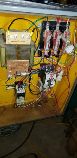
I don't have a wiring diagram, it looks like newer relays had been installed at some point. I can get the pump to run either by holding the on button or manually pushing in the relay. I got the spindle to work by manually holding in its relay. They should come on together and stay latched until the stop button is pushed.
1.jpg

Here is the spindle relay. My generated leg is L2. It is 244V, L1 and L3 are right at 240V.
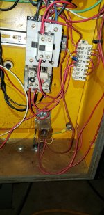
2.jpg

These two wires were hanging loose and taped over, they are labeled 3 and 104.
3.jpg
4.jpg
 
There are two contactors in the electrical cabinet. When you push the start button it pulls the pump motor contactor closed. The auxiliary electrical switch on the top of the contactor also closes the same wire electrical path as the start button. Once this happens the start button can be released.

The spindle motor contactor pull in coil also requires this auxiliary contact closure to operate.
As a guess there is something amiss with the pump contactor. There will be a problem if the control cabinet is using a neutral or ground wire to supply 120 volts to a 120 volt contactor coil. The generated phase from your phase converter will be at roughly 240 volts to ground. The other two leads will be at 120 volts to ground.

The transformer should be wired to convert the 240 volts supplied by any two power leads to 120 volts for the control circuit. This eliminates the need for a neutral wire and the problem of having a generated phase with a 240 volt potential above ground.
The white wire entering the cabinet with the three phase power may be the problem.

The first step is to identify which contactor is closing when the start button is pressed. You then need to verify that the incoming lead to the auxiliary switch has 120 volts.
The 120 volts should be supplied by the transformer. This can be verified by tracing the wires or by pulling the transformer fuse. If the switch is working and the voltage is correct, and the output wire is connected to the contactor pull in coil the contactor will remain on.
 
Last edited:
There are two contactors in the electrical cabinet. When you push the start button it pulls the pump motor contactor closed. The auxiliary electrical switch on the top of the contactor also closes the same wire electrical path as the start button. Once this happens the start button can be released.

The spindle motor contactor pull in coil also requires this auxiliary contact closure to operate.
As a guess there is something amiss with the pump contactor. There will be a problem if the control cabinet is using a neutral or ground wire to supply 120 volts to a 120 volt contactor coil. The generated phase from your phase converter will be at roughly 240 volts to ground. The other two leads will be at 120 volts to ground.

The transformer should be wired to convert the 240 volts supplied by any two power leads to 120 volts for the control circuit. This eliminates the need for a neutral wire and the problem of having a generated phase with a 240 volt potential above ground.
The white wire entering the cabinet with the three phase power may be the problem.

The first step is to identify which contactor is closing when the start button is pressed. You then need to verify that the incoming lead to the auxiliary switch has 120 volts.
The 120 volts should be supplied by the transformer. This can be verified by tracing the wires or by pulling the transformer fuse. If the switch is working and the voltage is correct, and the output wire is connected to the contactor pull in coil the contactor will remain on.
Today I replaced the pump contactor with a new identical unit and that didn't fix anything. This is the one that the start button actuates. Transformer is putting out 120V. When button is pushed I get 120 at the pump contactor and spindle contactor, but only the pump contactor actuates and then quits as soon as I let off the button.

Why would the white wire be an issue? 3 hots and a ground just like all my other 'dumb' 3 phase machines and they all work perfect.

I admit to not being very good with electric stuff, even as something as basic as what is in this machine. But I get the gist of how it should work and I'm just not seeing why it is not. It's not like this machine sat for years unused and I bought it sight unseen. It was in use until fairly recently and I saw it work. What I really don't get is why the pump contactor refuses to stay latched and why does the spindle contactor do nothing at all? Both pump and spindle motors run fine when each contactor is manually pushed in.
 
What I really don't get is why the pump contactor refuses to stay latched and why does the spindle contactor do nothing at all? Both pump and spindle motors run fine when each contactor is manually pushed in.
Does the wire that keeps coil latched run thru an auxiliary contactor? If it engages when button is pushed, but does not stay latched, maybe the problem is in the latching circuit? Just a thought.
 
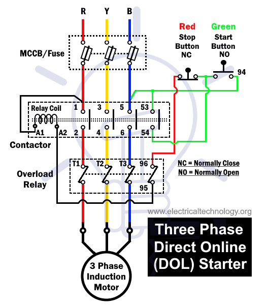
This is a schematic for a 3 phase motor starter. The black wire circuit in the first schematic is what is used to keep the contactor closed once the start button has been pressed. The fourth relay contact shown in the schematic with the black wires corresponds to the auxiliary electrical contact mounted on top of the 3 phase contactor in your post.

The wire layout in your grinder corresponds to the second schematic were the current overload relay can break the contactor coil start circuit. In this layout the pump motor will shut off if either the stop button is pressed or the current overload relay is tripped.
The second schematic is used to insure that the motor cannot restart itself if there is a overload condition.

The green wire circuit is used to keep the contactor closed when the start button is pushed.

The overload relay stop function can be defeated by connecting the terminal wires 95 and 96 together.
The overload relay will be tripped if there is a low oil level or excessive hydraulic pressure.

It may also overload if the hydraulic pump is running backwards. When you jog the spindle contactor the grinding spindle should rotate in the clockwise direction as seen from the front. The hydraulic pump will be turning in the correct direction if the grinding spindle is rotating clockwise.


Last edited:
You may want to look for the lube pump reservoir and make sure it's full or if there is a lube pump pressure switch. Many machines (not sure on your machine) have to build up lube oil pressure before the spindle start works. I also saw a Kent Grinder where you had to press the start bottom 2 times to get pump and spindle motor going.
 
This may come under real stupid suggestion but on your spindle relay at the bottom are screws 95 and 96.
With the disconnect off check resistance (Ohms) between these two screws, should be zero.
I assume you have pressed the little square red button just above these screws that resets this overload guy.
Curious that the spindle does not start when holding the button. Until it pulls in the run circuit will not latch.
Somewhere in my many file cabinets I have the original schematic for this but I can't seem to find it. Will keep looking.

Why is the spindle coil not getting power to make it happy? Who should be feeding me and why are you not?
Should run fine off your RPC and voltage on any leg to ground should not matter at all unless something really dumb was done in the refit.
Two taped off wires seem stange so that has me wondering. Where does 104 go?
It should be simple but hard for me to trace all the wires pictured in this spaghetti.

Bob
 
Last edited:
It's working! I bypassed the thermal relays (which did both show zero ohms between screws 95/96) and changed up the order in which the relays start. Before the pump motor was first, now I have the spindle motor first and pump hooked up to the aux contactor. No idea why it works this way and not the other. I did notice before that if I manually activated the pump relay, only the pump would turn on. If I activated the spindle motor relay then it would turn on followed by the pump a second later. I still find the whole situation very odd. The two disconnected wires I traced back to a limit switch, not sure how that figured into things, something to look into later. I would still really like to find a wiring diagram for this grinder.

Thank you for the help everyone!


Back
Top