DaveE907
Titanium
- Joined
- Sep 18, 2007
- Location
- Spanish Springs, NV
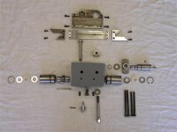
Recently assembled the carriage components that position the ELSR control rod. The first photo shows all the parts laid out that assemble into the unit attached to the bottom of the apron through which the control rod passes. It's a simple assembly but there are two timing matters to address during assembly.
The first is the knob (EE 3809) should point up at mid travel of the movable bar (EE 3804) at the rear of the unit. This isn't critical to operation, it's an appearance matter.
The second is the timing of the double sector (EE 3592) to the partial pinion at the bottom which rotates the control rod passing thorough it (I believe it's EE 3811, my print isn't very clear). The double sector is positioned so the portion with five full teeth are at the top and the portion with four full teeth engage the partial pinion. The longer boss on the double sector should be towards the tailstock end of the lathe. When timed correctly the keyway which drives the control rod will be at the bottom and the double sector will be positioned vertically as I've tried to depict in the second photograph. The, key, keyed washers, felt and snap ring were not installed here to help clarify the photo.
This is also how the components should be positioned when the control lever on the apron is in the "off" position when attaching the assembly to the bottom of the apron.
The third photo shows the control lever components that install to the apron casting. It's simple and should be positioned as noted above after assembly into the apron prior to attaching the lower ELSR unit.
One thing apparent when examining these components is Monarch carefully designed and provided lubrication paths for grease supplied through the Zerk fitting on the right end of the unit. It's an easily overlooked lube point but please don't. All lube for the carriage ELSR comes from that fitting, the oil in the apron doesn't service this unit.
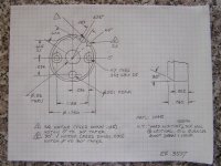
The forth photo shows the original ratchet (EE 3597) and the duplicate I made. The original was chipped and felt awful when using the control lever. The new one has case hardened teeth on a tough 1045 core.
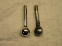
The fifth photo shows the original lever (EE 3599) and my replacement made of 303 stainless steel. This machine has remarkably little wear (less than 0.0005 on the ways for instance) but it has corrosion problems on some exterior parts. It's getting all new levers and knobs.
The first is the knob (EE 3809) should point up at mid travel of the movable bar (EE 3804) at the rear of the unit. This isn't critical to operation, it's an appearance matter.
The second is the timing of the double sector (EE 3592) to the partial pinion at the bottom which rotates the control rod passing thorough it (I believe it's EE 3811, my print isn't very clear). The double sector is positioned so the portion with five full teeth are at the top and the portion with four full teeth engage the partial pinion. The longer boss on the double sector should be towards the tailstock end of the lathe. When timed correctly the keyway which drives the control rod will be at the bottom and the double sector will be positioned vertically as I've tried to depict in the second photograph. The, key, keyed washers, felt and snap ring were not installed here to help clarify the photo.
This is also how the components should be positioned when the control lever on the apron is in the "off" position when attaching the assembly to the bottom of the apron.
The third photo shows the control lever components that install to the apron casting. It's simple and should be positioned as noted above after assembly into the apron prior to attaching the lower ELSR unit.
One thing apparent when examining these components is Monarch carefully designed and provided lubrication paths for grease supplied through the Zerk fitting on the right end of the unit. It's an easily overlooked lube point but please don't. All lube for the carriage ELSR comes from that fitting, the oil in the apron doesn't service this unit.
The forth photo shows the original ratchet (EE 3597) and the duplicate I made. The original was chipped and felt awful when using the control lever. The new one has case hardened teeth on a tough 1045 core.
The fifth photo shows the original lever (EE 3599) and my replacement made of 303 stainless steel. This machine has remarkably little wear (less than 0.0005 on the ways for instance) but it has corrosion problems on some exterior parts. It's getting all new levers and knobs.
Attachments


Last edited: