What's new
What's new

CNC 4'x8' router - ball screws vs helical rack

anchorman

Titanium
Joined
Dec 19, 2005
Location
Opelika, AL
We're looking at a couple of new machines for the shop I work in, and trying to get some real world info regarding ball screws vs helical rack. Which is better for wood?

The companies selling machines with helical rack on the X/Y axes argue that there is the issue of whip on long ball screws, but the designs I've seen using ball screws on X/Y have the ball screws stationary and the nut is integrated into the motor. Hard to see how one would have a problem with the screw length due to it rotating, when the screw itself is not rotating. Sag might be a problem, but given that the distance between the motor, screw, and the rails is fixed, I can't see that being a huge issue in use, except for it possibly causing wear to the screw over time.


Arguments in favor of helical rack are that it is usually the spur gear that is designed to wear, and it is easy and cheap to replace.

Arguments against helical rack are backlash issues, and keeping the rack itself clean... the cleaning part is a huge pain in the arse in my experience. I imagine running with some cleaning solvent is much easier on a ball screw, than trying to get every nook and cranny of a rack gear clean.​

Argument that the rack gear manufacturers make against ball screws is that they are actually less accurate over the distances involved in a CNC router designed for 4'x8' pieces of plywood and larger. It seems they are assuming in this argument that the ball screws themselves are rotating to cause movement, but maybe I'm misunderstanding?​
All the machines claim +/- 0.001" *repeatability* - What I understand that to mean is that they will return to the same spot on the table within that range. Cutting forces involved will affect actual cut accuracy beyond that, i.e. deflection of the bit, deflection of the machine, etc.

If anyone else has experience/insights, and can help me cut through the marketing jargon, I'd appreciate it!
 
I'd inquire on all machines whether they offer a compensation table for distance traveled, and if so what the discrete limits are (every 25mm, 200mm, etc.), As long as there is one you can get your machine calibrated (or DIY) using standard methods.

I'm team ballscrew, but it also matters as to anti-backlash method, grade of screw (almost certainly a rolled, not ground unit), and how they handle thrust bearings.

Frankly, I'd be more concerned about the design and robustness of the axis and bearing hardware, perfect motion control means nothing if the structure is a noodle and the bearings are sloppy.

If you have some specific machines in mind, post them for critique.
 
currently looking at Shop Sabre and CAMaster.


I've also considered techno CNC, and a few others.
All of these machines are about 3500 lb in weight, roughly the same class, though the shop saber "pro" model is a little slower overall, but this is not an issue for me. part fixturing ability is going to limit speeds to some extent, as is the 10hp spindle... We are not a production shop, and need accuracy and ease of use more than anything. I'd love to get the 16hp with the HSK-63F spindle instead of the 30 taper spindle, but I'd have to update the electrical service to the machine, and then get a newer more powerful vacuum pump too. all of which would probably kill my budget.
 
My machine is ballscrew and the two I setup and program at another shop are rack. Apples and oranges, mine is a 24,000 lb 30 year old machine, theirs are 10 and 5 years old and they could set on the table of mine. Previous job I had both ballscrew and rack as well on various machines.

In my opinion, given the choice and budget, I would only go with a rack for extremely long beds/travels, as in over 12ft. I'd also have the MTB or someone do a compensation on it like Milland said. In my experience, the mid level gantry machines with the racks that I have been around are noticeably different compared to my machine. Mine is old but has better motion control than the newer ones at the other shop. This I attribute to the MTB not taking the time to truly dial in the parameters and stopping at good enough. They are doing fine and most people would not know or notice anything about them.

It is worth considering the size of the ballscrew when comparing to racks, if they are cheap, the screw they use may not be big enough for the application, in that case you could have some of the concerns the sales guys talk about.

I know you didn't ask about it, but what do these two have for a control? I'd be asking as many current owners as possible about them to learn about the specific quirks and software etc you will need for each. I'd bet both of these have user forums to look at. I think the screw vs rack is likely less an issue than the machine as a whole.

Another tidbit, ask the sales guys if they can supply a full set of wiring diagrams/schematics for that specific machine. I chased an issue for way too long and I think it would have been quicker with a proper diagram. If I bought one new, I'd try to get all the documentation possible with it, because when it is 5-10 years old, the tech that is current on that machine may not be with the company anymore etc.

I know the shop Sabre uses win-CNC, unless you get into their most expensive machine that has some Mitsubishi controller. A guy I know at work has an older (maybe 10 years) shop Sabre machine and is very happy with it. I’m still waiting to have an in-depth conversation with the guy from Cammaster. I used their entry level machine at my old job, which used wincnc, but they have some sort of industrial controller now on their higher grade machines that are comparable to the shop Sabre.

We had an AXYZ am2c controller on the machine I am replacing, and I’m not in love with it, but I know how it works, when it gets overwhelmed, such as the machine trying to do too many moves in too short of a time frame, it just crashes, sometimes with the spindle plowing into the work. I’ve figured out how to make sure it doesn’t do that, by making sure small helical ramps into the material are steep enough, etc. I know the quirks and how to work around tolerance issues, but it makes it hard for other people I work with to use the machine and get acceptable parts.

I can do basic level G-code programming manually, by 99.99% of what I do is based on autocad drawings, and gets fed through fusion 360 for additional CAD work to clean up the drawings and then the CAM work to create the code is through that too. I’ve learned how to edit the post processor to make the machine work when it’s not fully compatible, but I don’t think that will be a problem. I don’t think I’ll have any issues getting fusion to output code that any of these machines can use.
 
If they're as light as you'd say, my gut says they're a little wimpy structurally, but that's just mass-prejudice on my part (I like my iron on the rotund side).

I'd haunt whatever machine-specific forums are available for the two (or other options) and see which has the least unhappy users. I don't care about glowing reviews, I want to see what the grumpy Gus's have to say.
 
I’ll definitely see what I can find out about calibration tables for both of these machines.
If they're as light as you'd say, my gut says they're a little wimpy structurally, but that's just mass-prejudice on my part (I like my iron on the rotund side).

I'd haunt whatever machine-specific forums are available for the two (or other options) and see which has the least unhappy users. I don't care about glowing reviews, I want to see what the grumpy Gus's have to say.

The shop Sabre sales guy seemed to understand the idea of the size/speed of the machines-vs rigidity, and the ones they build to go fast are definitely heftier pieces of steel. I was comparing overall weight vs max rated cutting speed of their machines,m, and they seem to go up accordingly in size of necessary components in the frame and screws/rails as they go up in speed and power.

I wish there were more specs available comparing the acceleration of various machines in addition to their top speed. It seems like that’s as big a part of maximizing throughput as anything. Our Current machine spends way too much of its time accelerating, and not enough at its actual programmed speed even when running at 300ipm. but if you bring up the acceleration too much more, it starts to overshoot. Top speed is kind of worthless if your machine can’t accelerate fast enough to use it, and doesn’t have a spindle that can take advantage of it.


I‘m unfortunately not a machine designer, so need to trust a little bit that these people know what they’re doing in 2023 to balance power against mass getting moved and the rigidity of the machine.
 
I am currently running a twin spindle gantry machine. I have 180" of X travel and 140" on Y with either spindle. X axis is gear rack driven using 4 Fanuc red cap servo motors driving preloaded gear boxes. Y axis is a 2" diameter fixed ball screw and each spindle has a rotating ball nut that drives it across the rail.

We only cut inconel, stainless and steel. You would never believe it if you didn't see it but this machine has taken a serious ass whoopin and still holds positional tolerance within 0.001".

if you are only ever going to cut wood, the simple test would be to ask them to face an aluminum plate with it. Any new machine should be rigid enough for that task. If they refuse, there is a reason.
 
I am currently running a twin spindle gantry machine. I have 180" of X travel and 140" on Y with either spindle. X axis is gear rack driven using 4 Fanuc red cap servo motors driving preloaded gear boxes. Y axis is a 2" diameter fixed ball screw and each spindle has a rotating ball nut that drives it across the rail.

Badass. Mind posting a few pics of the machine?

I'll presume the four rack drives are so the machine can use adjacent pairs to eliminate backlash? And this machine really would require a compensation mapping to get the full value from it.
 
Badass. Mind posting a few pics of the machine?

I'll presume the four rack drives are so the machine can use adjacent pairs to eliminate backlash? And this machine really would require a compensation mapping to get the full value from it.

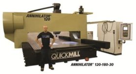
I would be fired on the spot if I even enter the facility with a camera. The machine is made by Quickmill out of Canada. Unfortunately they do not have a pic of this machine on their website.

It looks similar to this one except it has 2 independent cat 50 spindles and it is a bit bigger.
annihilator.jpg


You are correct on both accounts. It is interesting how they have it set up. X axis is the right side of the gantry and the left side is W axis. Each axis has a slave motor to control backlash and W is slaved to X to control motion from a single X axis output from the control.

Each motor has an encoder to track it's location and each axis has a linear encoder (glass scale) to track machine position. The control also tracks thermal compensation in live time to keep the gantry straight.

The more I dug into the manuals on this machine, the more I realized just how incredible motion control really is. A friggin gear rack driven milling machine, who woulda thought that would be possible? Lol.
 
I wish there were more specs available comparing the acceleration of various machines in addition to their top speed.
You can look at the size of the servo's driving each axis. to get an idea on the acceleration Obviously a machine builder could put in bigger servos than the machine can actually use so its not a perfect measure. Same thing for using the machines mass as an approximate measure for rigidity.

As a machine gets longer and longer travels a rack starts to make more and more sense as a proper sized ball screw starts to get prohibitively expensive. Awfully hard to tell though because some builders will use an undersized, or lower tolerance ball screw which might be worse than a rack.


Also, wtf is going on here, Milland and FM getting along in a thread?!?!
 
I would be fired on the spot if I even enter the facility with a camera. The machine is made by Quickmill out of Canada. Unfortunately they do not have a pic of this machine on their website.

It looks similar to this one except it has 2 independent cat 50 spindles and it is a bit bigger.
View attachment 391337


You are correct on both accounts. It is interesting how they have it set up. X axis is the right side of the gantry and the left side is W axis. Each axis has a slave motor to control backlash and W is slaved to X to control motion from a single X axis output from the control.

Each motor has an encoder to track it's location and each axis has a linear encoder (glass scale) to track machine position. The control also tracks thermal compensation in live time to keep the gantry straight.

The more I dug into the manuals on this machine, the more I realized just how incredible motion control really is. A friggin gear rack driven milling machine, who woulda thought that would be possible? Lol.
having linear encoders to give you absolute position, and you can get away with all sorts of things. on some level a bit of backlash is kind of irrelevant if you always know absolute position of the tool. I imagine it adds too much to the cost to have linear encoders installed on something like a CNC router. for a mill that had to have better cut tolerances, surely worth it, though.
 
I'd inquire on all machines whether they offer a compensation table for distance traveled, and if so what the discrete limits are (every 25mm, 200mm, etc.), As long as there is one you can get your machine calibrated (or DIY) using standard methods.

Can you explain a bit more about what this is? I know every controller out there allows one to adjust the number of steps on the motor per inch of travel. I noticed on the current machine that has uneven wear on the rack gears that if I dial in the calibration to make accurate parts on a small scale (say 4" squares), that the travel is off over the length of the table. 0.0005" over an inch of error adds up to almost 1/16" short over 8'. The biggest issue is when this is inconsistent depending on where you are on the table. These compensation tables of which you speak, are they a way of telling it to move a few thousandths more when the machine moves 48" vs when it moves just an inch.
 
The way it was explained to me 15 years ago was somehow a person would measure over the full travels of the machine to a very high level of accuracy and precision, records the difference in actual measured position and what the machine thought it was at. Then they somehow built the compensation table for the control to apply to the movement of the machine. I don't know which controls can do that, it may be only an option on more expensive control packages. I think I was told at the time an independent company used lasers somehow to measure. I do think that the higher end MTB's use this method at least to establish the left/right compensation on a moving gantry to keep them moving perfectly together, may do it to each machine now, I don't think the one that told me about it did for every machine at that time (This is one thing I think is just slightly off on the machine my customer has. Every once in awhile I get some feedback that I can feel in the machine that makes me think the two servos driving the gantry are not fully in sync together.)

Just remembered now seeing in one of Abom79's videos of setting up his long travel mill that the install tech did some compensation procedure on it and I think it was very automated. You might check it out, it was within the last few months I think.

I think as you found out if you just change the parameter to how far each step is, it will not be accurate over any distance, that's why you need to use actual measurements to compare to and then somehow reference it for that axis.
 
The Weeke I sent to the scrap heap had about an 11 foot double anchored X ballscrew with rotating nut. <50 mm dia. It would vibrate slightly doing a full X axis rapid. It also had an X scale. Funny part was the X scale was adhered to a thick piece of plastic. That plastic was buckled slightly after a night with light rain. Sad, all of the mechanicals were solid. 26 year old control and hundreds of brittle exploding air hoses.
 
Just remembered now seeing in one of Abom79's videos of setting up his long travel mill that the install tech did some compensation procedure on it and I think it was very automated. You might check it out, it was within the last few months I think.
After watching that, I don't think anything that we are going to get is going to have that type of compensation available!
 
When I was looking into routers in this class, I thought that the DMS Patriot was more impressive than either the shopsabre or the cammaster. For what that's worth.


Back
Top