What's new
What's new

Coming Soon: A Beam 18" Featherweight Parallel/Level. And more lengths later

dgfoster

Diamond
Joined
Jun 14, 2008
Location
Bellingham, WA
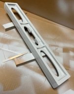
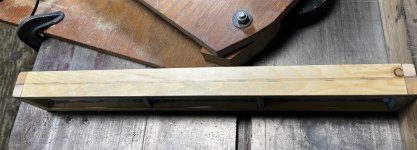
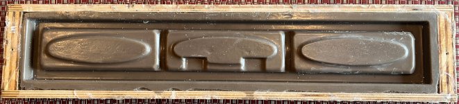
I have been sketching an 18" beam-like straight edge that will provide a mounting point for a precision level vial. It will be about 2.5" high and 1.5" deep. The depth will really be up to the end user as it will be designed so that it can be left full thickness or milled on the front and back to trim it down to about an inch thickness if desired.

In general terms it will have three 6" segments. Each six-inch segment will be separated from its neighbor by a vertical (likely curved) rib. Each segment will have a single oval window occupying much of the web of each segment. The central ovoid will have an oval outline but a rectangular window into which a level vial can be mounted, if desired. The best candidate for that vial that I am aware of (if there are other better choices, please let me know)
[h=2]4-3064-20[/h][h=2]Drawing Available[/h][FONT=&quot]Highly sensitive mounted tubular level with adjusting studs, nuts, fulcrum and base with instrument black finish. Sensitivity: 20 seconds per division (2.0mm). Overall size: 3.00 inch L x 1.25 inch W x 1.25 inch H. Reference drawing for other dimensions and position of three (3) mounting holes.

[FONT=&quot]The depth of this vial requires the 1.25" depth. For those not using the vial, it may be desirable to mill off some of the thickness.

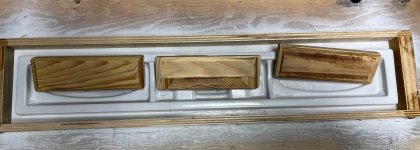
In general the lines for the casting will be pleasing to the eye and graceful as I believe a tool should be both very functional and as beautiful as possible.

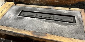
The castings, as are my other castings, will be made from ductile iron returns. (The castings will not themselves be ductile, but using ductile returns assures very high quality metal as opposed to scrounging junk, throwing it in the pot and pouring whatever comes out.) These castings will continue in the tradition of Featherweight castings being of the highest quality and they will be properly thermally stress-relieved as are all the castings I sell.

I think I will be able to supply these castings at a lower cost than my prisms as the simple beams will not require the more complex casting techniques required for the multi-tool prism forms.

If anyone has suggestions, I'd be most appreciative.

My target is to have something cast in the next 6 weeks.

In the long run I hope to cast 24 and 36 inch versions as well. Their dimensions will be a bit greater in depth and height. Every effort will be made to keep these as light in weight as possible and still retain excellent rigidity.

Denis[/FONT]
[/FONT]
 
I would suggest that 20 seconds per devision (1 thou in 10") is on the very outside of precision levels. you might need to see if they do more sensitive vials.


Starrett's 199Z 15" level uses a 10 second vial.

Geier and Bluhm and LevelDevelopments do make more sensitive vials.

For instance Geier makes a 4-6010 and a 4-6011 mounted vials for about 300 dollars with sensitivities of .0003 and .0005in/ft respectively.

LevelDevelopments makes a mounted vial for about 400 dollars and a bare vial of .0005/ft for 42 dollars.
Precision Ground Glass Spirit Level Bubble Vials and Phials

Some of these vial mounts are 6" in length.

I very much appreciate you speaking up, Mark. What vial do you (and certainly others should chime in) would be ideal for such a level/parallel. It is very easy now to erase pencil lines on paper, but it is a lot more work to redesign patterns later. I'd like to come up with a design that works well for a variety of people, It does not have to fit just one vial by one manufacturer and probably should offer a range of options since some folks have raised concerns about overly sensitive vials in the past, for example.

Then there is the question of mounting. In my shop I can reach in drill and tap holes in features with overhanging casting segments. I fabricated an offset tool for just such an operation to allow mounting level vials in my prisms and at the same time not "violate" the sole of the prism since it is not necessary to drill from outside the sole up into the sole with such a setup. However, in discussing this by phone last night with Forrest Addy, I think it will be best to design the casting with the assumption that the end user who intends to mount a vial will will bore (and counterbore as necessary to accommodate tap shaft size) holes from the bottom surface of the level and up to the mounting window. Then they will ream the counterbores and plug the holes with cast iron stubs that I would supply as oversized short round bars. The assumption is they would turn the bar to make a neat fit into the reamed holes "gluing" the plugs in with Loctite. Such a hole should present no problems to scraping and would be nearly invisible on the scraped surface---agreed?


Denis

Added: I also came across this one available for 72 Euros only 3" long and .04mm/M accuracy.
https://www.roeckle.com/epages/6211...34/Products/LibiH/SubProducts/"LibiH 62x0,04"
 
Last edited:
Drilling and plugging sounds like a reasonable approach for most people adding a level vial. Don't discount modern adhesives and filler materials which are increasingly used in creative, interesting ways.

I was told by one level vial manufacturer that Kingway specified 10 second vials, just for comparison.

Just musing out load, a more sensitive level might seem less twitchy on a longer device since it requires a larger displacement on one end for the same angular change.

That is a good point, Tom.

Here in the most preliminary form is what I am thinking of. As presently drawn it will finish machining at 2.5 inches high and 18 long. The webs will be 1/4" thick except for the area under the central ovoid window. There is will be 7/16" thick to allow for mounting holes to be bored and to provide a wide enough surface on which to mount the level vial if desired. I'll probably have the flat side of the central window stand 1/8" higher than its intersections with the cutout to allow stock for machining. It will be 1" deep (the tubular vial rather than the base-mounted vial allows thinner section) and the outer surfaces that form the outer rectangle will be 3/8" net. I'll probably cast them 1/2" thick to allow for plenty of stock for clean up. All of the vertical ribs including the ends will not be flat on their faces, but rather gently concave equally fore and aft. This latter touch is mainly for aesthetics but will also provide a little clearance when placing the parallel near surfaces that themselves may have protrusions.


The central window should allow plenty of room for a variety of levels though not the G+B mounted level I linked in the first post. It requires 1.5" depth. This casting will net out at 1" machined and scraped depth.

Sketch Preliminary.jpg

Denis
 
The collection of levels in my shed are:-

20220506_201117.jpg

From back to front:
8" square level with 0.25 thou in 10" (5 second) vial. has been used for checking squareness of the mill's knee during rebuild.
12" level with 0.5 (10 second) thou in 10" vial
8" adjustable level with 1 thou in 10" (20 second) vial. Originally used for aligning steam turbines. Has been used for woodwork :)
2 0.1 thou in 10" (2 second) Level Developments vials that will be going into the KingWay jig that I'll need when I rebuild the surface grinder.

The sensitivity needed for a level can vary greatly according to the use it's put to, having a range of sensitivities available can be a good thing.

PS: Do you want to learn how to suck eggs, Grandma? :o
 
Mark,
I was puzzled by the last sentence above. So, Google to the rescue: “ Teaching (your) grandmother to suck eggs is an English language saying that refers to a person giving advice to another person in a subject with which the other person is already familiar (and probably more so than the first person).”

Now I get it. ;-)

Denis
 
I've started to cut wood for the new pattern. It will be made of Baltic birch plywood for the web, the flanges will be yellow cedar and bass wood. This will be a split pattern so once it is all assembled, I will split it down the center with my table saw. That will reduce the web from its current 3/8" thickness to 1/4" thickness. And I am making the flanges both thicker and wider than the final casting and the machined casting. My idea is to make it a bit heavier in the flanges than most people will want. But, it can be very quickly be pared down as their taste may dictate to the final dimensions desired. And there is more to be done to the middle window to provide for level attachment. But I thought I put up the first baby steps toward making the pattern. This is really fun work. I just plain LOVE the smell of yellow cedar.

Once this wood pattern is finished, I will make a plaster mold from it and then cast it in a commercially available polyurethane casting resin made for the purpose. That way I can retain the original free from the usual bumps and bruises of normal molding and handling. The plastic working pattern will be used to make the green sand molds so this can be cast in iron (or aluminum if so desired.)


Preliminary sketch with masonite oval pattern to be transferred to steel template.
Sketch Preliminary.jpg


Template is 1/4" To make it possible to true up on my belt grinder, I split the cutout. Using the small contact wheel attachemnt allowed grinding the inside curve as easily and quickly as if it were wood.Grinding inside of template.jpg


I allowed for the kerf previously made and tigged the the two template halves back together.Template welded and drilled.jpg

Here it is attached to the piece of Baltic birch that will form the web and used to cut out the oval. I first removed a lot of the waste on my mill. The template made cutting the windows really quick and easy.
Cutting out the ovalwith router.jpg

You saw it here first! My first glimpse of it as a 3-D object.
Rail stock and web prepared..jpg

Draft is already cut into the flange piece. The windows will be rounded over and the middle window built up on its lower edge. More photos as the piece takes shape.

Comments welcome.

Denis
 
Next step after rounding over the windows was to glue up the web and two flanges. Getting started with everything square saves a lot of work later. The 2-4-6 blocks were a convenient aid in squaring up. The flanges will be trimmed to the length of the web once the glue ("5-minute" epoxy) is cured.

Gluing up the main assembly.jpg


Don't worry---I placed the blocks at Airy points! ;-)Gluing up.jpg

Denis
 
So, now the pattern is basically cobbled together. Now I am paring to its casting size. It is tempting to trim down to see what it would look like after it is machined. But I have to resist that urge and leave the material that will provide plenty of allowance for machining. I was originally thinking of casting the vertical end flanges with a sweeping curve. But I think I’ll leave them straight. Anyone who wants to relieve them for clearance or aesthetics can so so in a few minutes with a die grinder.

Mockup.jpg

You can see the gaps between the cut ends of the long flanges and the end caps.
Draft visible.jpg

Gluing the end caps on.
End caps (Draft visible).jpg

All outside corners will need to be rounded over and fillets need to be added to inside corners. And the lower edge of the middle window needs to be modified for level vial mounting. Still and all, this pattern has progressed pretty rapidly.

I am very anxious to cast it. I think it will weigh on the order of 10 to 12 pounds as cast and would machine down to 7 to 10 pounds.


Denis
 
Today I set the pattern up on the mill to true up all edges and flange surfaces. Because I want the web to be accurately located on center and parallel to the flanges I fixtures it with the web located on 1-2-3 blocks. Then I used a nice new 3/4 carbide end mill to trim the flange faces and sides. This was important on this pattern as users will be location mounting holes based on those surfaces and it would be aggravating if some distortion of the casting caused them to make an error. Of course, the casting will distort slightly, but this design should not bow or twist to any noticeable degree given it symmetry. Inspecting the pattern now shows everything to be within a few thou of “plumb and true.”


Prior to bolting down
1-2-3 Block web setup.jpg

Overview
1-2-3 Block web setup1.jpg

Side view showing pattern suspended on blocks.
1-2-3 Block web setup side view.jpg

Next up is rounding outside corners over and then installing ribs, center window build-out, and fillets for inside corners.

Denis
 
I have (finally) decided how to handle the build out of the middle window to accommodate level vials. Numerous options were considered some of which were ugly or awkward or too flimsy. I wanted to not interrupt the curve of the middle window unduly and still offer a mount surface that would work for a variety of vial lengths and would be very solid and easy to use.

My plan is to add columns to the middle window each column being 1/2" front to back. Along the length of the window the column will be a halfi inch in width being .625" from center to center of a solid shape which would be described by taking a 3/4" high 1/2" diameter rod and moving it along the long axis of the window .625 inches. So, it will be a sort of hybrid rectangular solid with semicircular ends. It will straddle the web. It will allow vials of about 2.75 to 4.5 inches in length to be attached securely to the level. With some modifications sizes outside this range could also be used.

I had a couple hours in the shop today and used the time to make a die in which to cast Freeman Supply's Repro polyurethane 2-part plastic. The repro is new to me and this will allow a small-scale trial of its use. Later on I plan to cast my wood pattern in Repro to make working patterns. This will save wear and tear on the master pattern and allow me to have more than one pattern for use which should speed production.

Here are a couple of pics of the "die' which is quite crude by die making standards but which should serve the purpose. It was made by tack welding two pieces of hot-rolled 3/8" bar together and then milling out a pocket which is stretched fore and aft 1/8" to allow for the kerf to be made when the pattern is split along it long axis.while it is standing on one of tits flanges. After the pocket was milled, I drilled and reamed 1/4" holes and then milled away the tacks. I did a little polishing of the interior and then fitted pins which will align the two halves. (Yes, I could have just milled solid columns rather than making the die. But, I'll never learn anything new if I keep on doing things the way I have previously done them. ;-) )

Here is the tacked-up block milled out 3/4 deep and 5/8" wide.
Die 4.jpg

Drilling and reaming the alignment pin holes.
Die 3.jpg

Pins in and halves separated
Die.jpg

Partially closed. The short round cuts on the four corners of the seam are where the tacks were milled away to allow the block to be split.
Die 2.jpg

Tomorrow I will mix up a little repro and cast the columns. I'll remove the Repro after it is semi-solid. That way it should not stick too tightly to the mold even though the mold is by no means polished. To install the column, I'll cut a 1/4" wide slot it in so it can straddle the web.

[Credit due to Forrest Addy who patiently listened and helped me decide on which design option to chose for the columns.]

Denis
 
Last edited:
And here is how it is going to be configured:

ready-for-fillets-jpg.364720


Here is how the Repro looks popped out of the mold. I did polish the mold some using a simple wood dowel split for 1 inch with my bandsaw and then loaded with flaps of Si-C paper. I chucked up the dowel/paper in my hand-held drill motor and used 120,220, and 600 grits, spending maybe a total of 5 to 10 mins polishing the mold. Oh, the dimple in this casting is not a fault of the plastic. I tested the degree of set as time went by and pressed the dimple into the half-set plastic. No problem as it machined out anyway. See below.

column-molded-jpg.364722


And here is a close-up of the machined cast bolster. This Repro Fast Cast One is really nice to work with. It machines very easily and cleanly holding dimensions much like Delrin. There were no bubbles in the cast plastic whatsoever. The material demolded cleanly one hour after pouring. It seems to have quite good structural integrity. I doubt it is quite as good as Delrin in that department. But it is good and, though purpose-made for pattern work, is a good enough plastic to be used in other applications.

bolster-jpg.364721


So, I am really pleased with the new material and I also like the general feel of the pattern in the hand. Those oval cutouts work as very nice grip points. The bolsters should provide plenty of mounting opportunities and I hope folks don't find them too ugly. They were the best compromise I could come with considering form vs function.

Tomorrow begins the fiddly work of making fillets (I'll post a couple pics of how I use epoxy poured into the inside corners to make a "perfect" fillet with the least work of any method I am aware of) and filling all manner of tiny bumps and bruises with Bondo, cyano glue, shellac, and lacquer. You can already see bits of bluish Bondo here and there on the pattern.

Comments/suggestions welcome.

Denis
 

Attachments

  • Column molded.jpg
    Column molded.jpg
    600.4 KB · Views: 149
  • Bolster.JPG
    Bolster.JPG
    221.1 KB · Views: 154
  • Ready for fillets.JPG
    Ready for fillets.JPG
    787.1 KB · Views: 154
In the middle of the night I heard a grinding sound in my head, then a couple of clunks and a scraping sound and then finally some whirring....;-) It was then that the idea of using the Fast Cast Repro for fillets rather than using epoxy, as I have done previously, finally occurred to me. The epoxy did a fine job of fillet-making. But it took at least 6 to 8 hours in a warm shop to cure enough so that I could reposition the pattern and do another set of fillets. I incline the pattern about 30 to 45 degrees perpendicular to the fillet line I am filling to allow the viscous liquid to self-level and then cure. I'll do the same with Repro, but the gel time is 6 or 8 minutes and it is fully set in an hour. Chances are I can do a new set only a half hour after starting the first set. Since most patterns require at least 8 sets, using the Repro will greatly shorten the time span needed for getting all the fillets done.

The viscosity of the Repro is quite similar to that of the West System epoxy I have used in the past. The Repro, however, has no tendency to produce bubbles. So, I don't need to pop bubbles with the Mapp torch like I did with the epoxy. That's no big deal as the torch step was easy and kinda fun, actually. But it is just one less thing to think about.

Repro Fast Cast Fillet.JPG

Denis
 
After making 16 different "sets" of Repro for the fillets and cutting the draft on the outside surfaces of the pattern, it was ready for primer. I use a 2-part high build primer as it cures rapidly, covers a variety of "sins," and sands very nicely. There will be a few slight defects that will need some Bondo despite the primer. But, overall, things are looking quite positive. If all goes well, I should be able to make a test casting early next week. Can't wait.


Here is the general setup used to make a controlled 2 degree cut on the outside edges. Each surface gets two cuts that meet at a crown in the center. The red circle just outlines a modification I made years ago to my fence that secures the far end and prevents deflection.

draft-cutting1-jpg.365017


Very small movements of the fence result in large changes in the width of the 2 degree face. A DTI helps make those adjustments accurately.

draft-cutting2-jpg.365018


The resulting crown and relief made by the cuts.

draft-cutting3-jpg.365019


Before splitting the pattern right at the crown, I am applying paint. First is the primer and it will be followed by lacquer.

draft-cutting4-jpg.365020

With a coat of primer.
paint1-jpg.365021


The filleting material worked very well. Only a couple areas will require touch-up and that is for aesthetics, really.


Denis
 

Attachments

  • Paint1.JPG
    Paint1.JPG
    248.2 KB · Views: 162
  • Draft Cutting4.JPG
    Draft Cutting4.JPG
    850.8 KB · Views: 161
  • Draft Cutting3.JPG
    Draft Cutting3.JPG
    271.4 KB · Views: 159
  • Draft Cutting2.JPG
    Draft Cutting2.JPG
    522.1 KB · Views: 160
  • Draft Cutting1.JPG
    Draft Cutting1.JPG
    1,010.4 KB · Views: 159
After getting a couple coats of two-part high-build primer and shellac on the pattern and doing some light sanding and filling a couple small areas with Bondo, I put a couple coats of lacquer on the pattern. I'll let it dry and harden tonight. In the morning I'll drill a couple of 3/16" registration pin holes, one in each end. Then, after mounting a newly sharpened blade in my table saw and drinking a couple cups of coffee, I'll set it up on the long narrow face and split it in half. The resulting halves will be attached in registration to opposite sides of a matchplate and then I'll try molding it in sand. Once any molding kinks are ironed out (drum roll and brass flourish), I'll have a go at pouring a test casting.

In the cardboard "paint booth." I use shellac and lacquer since they are quick drying and the lacquer provides a very smooth hard,surface. The high-build primer sands wonderfully and tends to cover minor surface imperfections.
In the cardboard paint booth.JPG

Drying and hardening.
Letting the lacquer fully harden.JPG

Denis
 
Last edited:
I did get the pattern split without incident. I was very careful and did use a newly-sharpened blade and a pressure-guide to keep the cut straight. I was a bit worried about the two plastic bolsters wondering if one of them might crack or be dislodged. But everything went smoothly.

Then I started gluing them onto the 3/4" plywood matchplate. I used thin cyano to attach the two pieces and was super careful to not get one side upside down with respect to the other side. Making such a senseless error would have been so easy for me. I checked and rechecked before committing glue. I did drill the registration holes and thought later that one fairly fail-safe method of ensuring I would not make a reversal would have been to bore just one centered and one well off center. As it was both were dead center. So, flipping the wrong way would have been easy.

One new technique for me today was making micro-fillets using thin cyano. Where the pattern meets the plate I wanted to provide a tiny fillet. Something on the order of .016 inches would have been fine. So, after getting the two halves glued down correctly, I spread a thin bead of liquid cyano glue along the join line. Surface tension pulled it into a nice radius. I knew that spraying the wet fillet with cyano activator would cause it to foam up into an ugly hard mess. But I was impatient to have it set up and open thick wet cyano sets pretty slowly. So, I stood back about three feet and just gave the wet cyano a couple of very brief puffs of activator. It worked! After about 30 secs the cyano had set but it did not foam. Yes!

Here are some pics. Eventually I intend to pour two castings per flask. I'll make a copy pattern using Repro. For now I am just mounting one front and back pattern half to the plate figuring there may be some bugs to work out. That is why the pattern is offset from the midline. I Bondo'd the registration holes. The surface of the matchplate has a couple of casual coats of shellac. The plate itself will not be highly finished as experience has shown the flat surface of the plate need not be particularly refined to pull cleanly. Different story for the vertical parts of the pattern, of course.


Matchplate5 Split.JPG Matchplate4 Split.JPGMatchplate2.JPGMatchplate1.JPG
The cyano micro fillet:
llet using thin cyano.JPGI hope to finish setting up the plate tomorrow (I'll hand cut the runner, splash basin and gates for the shake-down casting sessions. Once I know what works, I'll convert to permanently adding those features to the plate.)

Denis
 
Continuing the saga of bringing a new parallel to life: I got the pattern painted using lacquer, waxed it, coated it with graphite and talc and gave it a whirl packing it with green sand. Overall, it worked out really well. There was one tiny pock mark in one corner of the drag half of the pattern. I had looked the pattern over pretty well I thought. But the sand "found" the pockmark causing a repeating small area of cracking of the sand. The area was small enough and not dislodged. So, I was able to very gingerly tamp it back into place. I think it will hold up to the flow of molten metal. I'm not certain it will. But I think it is likely to be OK. Other than that problem the pattern pulled very nicely once I figured out how to lift the matchplate without bruising areas of the mold. (Each new pattern requires some time to learn its peculiarities. It would be very rare to just pack a new mold and have it pull just right the first time and every time thereafter.)

Here are a couple pics:

20 second video survey of painted match plate.

The pockmark was in the cope side of the pattern right in a corner.
packing-mold-pock-mark3-jpg.365338


Closer pic---the actual defect is in the center of the dotted circle.
packing-mold-pock-mark2-jpg.365339

The drag side of the mold. Later I cut a splash basin, runner and gate into the sand.
packing-mold-jpg.365340


The cope side. I will place a ceramic filter in the srue base. You can just see the sprue mold deforming the sand to the left and slightly below the mold cavity below. It will be above the splash basin in the assembled mold.
packing-mold2-jpg.365341


I'll fix that pock mark with a tiny bit of Bondo.

If all goes well, I'll pour the mold and an 18 tomorrow. That's the acid test.

Denis
 

Attachments

  • Packing Mold2.JPG
    Packing Mold2.JPG
    892.9 KB · Views: 137
  • Packing Mold.JPG
    Packing Mold.JPG
    688.1 KB · Views: 137
  • Packing Mold Pock Mark2.JPG
    Packing Mold Pock Mark2.JPG
    210.7 KB · Views: 138
  • Packing Mold Pock Mark3.JPG
    Packing Mold Pock Mark3.JPG
    346.8 KB · Views: 137
Today was the day to cast the new pattern. Lo and behold, it poured just fine! I was actually somewhat surprised as I usually expect an unforessen problem or two to crop up. But, this time fate was kind.

Here are a couple pics. There were no filling defects of any kind. This is a nice clean casting. Tomorrow it will be properly stress relieved along with the 18 I also cast today. Casting Number One3small.JPGCasting Number One2small.JPG

The casting feels very nice in the hand. It weighs 8 pounds 13 oz as cast. I think about a pound or 1.5 pounds would be machined off for finishing.

It cast surprisingly straight. A feeler gage measures the bow in the face as about .025" for the 18 inch length. The iron in this will be very soft and uniform I am certain.

This casting had no lettering. I think the final casting will have just "FF" on one bolster and "2022" on the other bolster. Not sure about that yet. There is very limited room for lettering on this casting.

I set out to have this cast 6 weeks from May 5. Normally my projects take twice as long as hoped. Not this time!

It was a very good day at the foundry today.

Denis
 
Last edited:
Well, jobs done now that the pattern cast successfully, right? Nope. I am making a working match plate and dedicated flasks for casting this pattern on an ongoing basis. The wood master I used for the test casting will be set aside to save wear and tear on it and urethane plastic copies of the pattern are in process. Ian making copies because

1)The repeated handling and mold ramming take a toll on patterns
2)Having an original and copies reduces the chance that I’ll have to go through the substantial work of remaking this pattern. I'll keep the original at home and the copy at the foundry. Again a safe-keeping feature.
3)Plastic patterns are tougher than wood
4)By putting 2 sets of plastic patterns on one match plate I can ram two molds for the same work expenditure as one.

The copying process can be done using various materials to make a negative copy of the original. Plaster of Paris, silicone rubber, and urethane rubber are most commonly used each having pluses and minuses, but each, properly used, can faithfully capture fine detail in the original. I am using two-part urethane to pull the copy mold.

Here's the process for anyone who cares to look.
First, you need a dam around the original wood pattern. I made it out of Baltic birch and sealed it in place with silicone glue between the match plate and dam.
rubber-mold-frame-jpg.365773


Next came spacers which reduce the volume of expensive urethane rubber needed and strengthen the rubber
rubber-mold-spacers-jpg.365774


Attached to backing piece which becomes a permanent part of the rubber mold
rubber-mold-spacers-atttached-to-lid-small-jpg.365775


The backing board was attached to the dam after viewing and monitoring holes were bored with a Forstner bit
rubber-mold-lid-with-holes-in-place-jpg.365776


Then the two-part urethane rubber was poured after carefully leveling the mold.
rubber-mold-with-urethane-poured-jpg.365777


Ater an overnight cure, the mold separated cleanly from the pattern. (One nightmare scenario would be to have the urethane bond tightly to the mold. To prevent that wax, PVA and silicone were applied to the wood pattern
urethane-mold1-jpg.365778


Next, the mold was filled with a commercial purpose-made two-part hard rigid urethane. I'm at my image max for this post. So, on to the next post.

Denis
 

Attachments

  • Rubber Mold with urethane poured..JPG
    Rubber Mold with urethane poured..JPG
    868.9 KB · Views: 115
  • Rubber Mold lid with holes in place.JPG
    Rubber Mold lid with holes in place.JPG
    735.2 KB · Views: 115
  • Rubber Mold spacers atttached to lid small.jpg
    Rubber Mold spacers atttached to lid small.jpg
    810.9 KB · Views: 117
  • Rubber Mold spacers.JPG
    Rubber Mold spacers.JPG
    682.1 KB · Views: 117
  • Rubber mold frame.JPG
    Rubber mold frame.JPG
    674.4 KB · Views: 117
  • Urethane Mold1.JPG
    Urethane Mold1.JPG
    517 KB · Views: 115


Back
Top