What's new
What's new

Converting Monarch 10ee motor-generator 3-phase to single phase, Steelman method

I plan on using the original start-stop switches with the associated relay. I will need some education about "heaters". I suspect I will need different values for the heaters, know how to calculate the size and figure out where to get them. Any hints?

As an aside, members may notice the new 8" x 12" x 2" junction box blocks access to the rear M-G grease zerks. I replaced the M-G and the Exciter bearings with sealed rather than shielded bearings and the grease zerks are no longer needed. If I live long enough for this to be an issue I'll shimmy up to this unit in my wheelchair, drag out the M-G and replace the bearings.
 
Last edited:
In order to size the heaters, it is necessary to have current readings for the run winding and the start winding. These will be different. A "clamp meter" is required.

Alas, there is only room for two heater blocks, and the code (and good practice) requires the heaters to be placed after any capacitors.

Also, you can add power factor correction to the run winding and reduce the amp draw, somewhat.

What you have implemented, and have documented, a well-defined "skeleton" conversion which deserves to be "fleshed out" for operational convenience as well as for operational safety.

I will be pleased to assist you in adapting the main contactor as your (M-G) controller.
 
... In this box the upper left relay has a constant arcing across the contacts (while running the spindle in either forward or reverse). What is its function and it looks adjustable. What is the correct way to adjust it so it doesn't arc across the contacts which I presume it shouldn't?

null_zps47b8c6e2.jpg

That's the FA (Field Acceleration) relay. Its job is to bypass the spindle motor field control potentiometer and apply full field to the spindle motor when the armature current is high, as when the motor is accelerating under load. It has one coil that's in series with the armature (to sense the armature current) and another coil that's just connected to 115VDC and appears to be used as a bias coil. I don't know at what armature current level the relay is supposed to operate.

Is the relay cycling on and off, or what? Is it happening at low speed settings on the speed control?

Do you have a meter with a 20A DC mode or a clamp-on ammeter that reads DC (most don't)?

BTW, bravo on the work you've done and the nice way that you've documented it!

Cal
 
"end-product CAN also be used AS an RPC for other external loads when the 10EE is not in-use for turning"

I'm not clear how this would be true.

The three-terminal motor with 0-, 120- and 240-degree windings is turned into ... effectively ... a four-terminal (two terminals, net, to external equipment) motor with 0- and 90 degree windings.
 
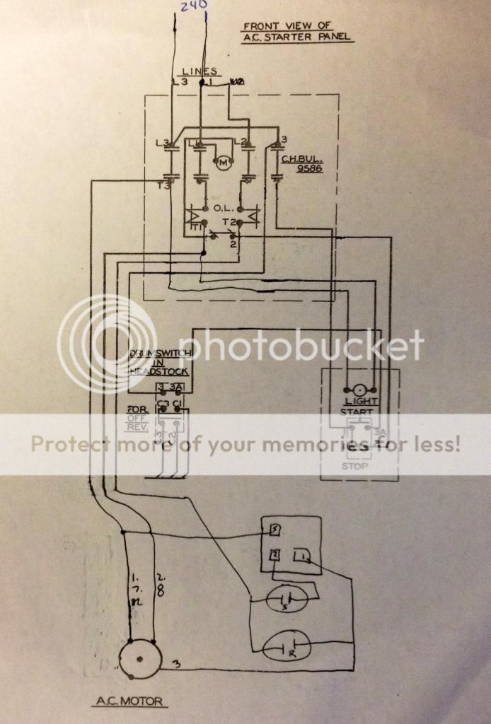
So I'm thinking I can use the original 3-phase starter on my single phase conversion despite the fact the original starter only has two heaters. My logic is if I had a single phase motor, I'd really only need one heater as all the power is going to thru at least one heater and therefore two heaters on a single phase motor is redundant. In my schematic to follow, all the power goes thru relay contact L3 (1,7,12) which does not have a heater. A part of the power for the paralleled field (2,8) goes thru L1 which has a heater and a part of the power goes thru L2 which has a heater for the out of phase field (3). Thus the individual windings (fields) are protected. You will notice I eliminated the transformer as my light bulb in the on switch is rated 240 volts. Guess I'd rather keep similar voltages in the one conduit they go thru. Anyone see a potential error in this thinking?

 
Last edited:
Please review my original post, and the schematic diagrams attached thereto.

In that post, I intentionally split the run winding across two starter contact sets, with the start winding through the remaining contact set.

Then, in the "return" which is the combination of the two run windings, I place an overload, and the return for the start winding, I place the second overload.

The returns necessarily must be connected before the starter, but after the fusible safety switch.

This, then, will provide a motor controller with overloads in both the run and start windings, and a lock-out/tag-out capability for all.

The Cutler-Hammer starter has overloads which are separate from the contactor, and these may indeed be wired as I have described.
 
Notice that the headstock's drum switch (same as the ELSR's microswitches) are implementing a "lockout" function.

Namely, the FWD/Off-Brake/REV switch MUST be in the Off-Brake position in order to start the drive system. All 10EEs operate this way.

IOW, the switch sections are N.O. if in FWD or REV and are N.C. if in Off-Brake.
 
Recently got a 10EE turret lathe with a MG drive. Originally assumed it was functional, however it had been converted to a 180VDC controller.
So I opened up the MG junction box and........... The godless savages had dyked off the leads. The external star point is still in place so I have been able to determine the 1,2,3,4,5 and 6 leads. Here's the problem: Once I have found the internal point for 10,11 and 12 (unlabelled I assume) how can I correlate those windings to my known ones. That is, how can I ensure that the two leads 7,10 are the correct winding to go with the 1,4 winding.
 
Determining field winding leads.

Here is some more detail re: my question above.

DSC01260[1].jpg
I am trying to determine the 7,8,9,10,11 and 12 points in this field coil. The 7,8 and 9 ends had been cut off, so I cannot tell which wires are 10,11 and 12. So I ripped into it....... and splayed out the six individual windings. The purple tabs are for the star point leads (10,11,12). The question for the motor experts is: Are the 7-10, 8-11, 9-12 windings across the diameter from 1-4, 2-5, 3-6 or are they adjacent to them? If Adjacent; are they clockwise or counter to their mating windings.
I am going to replace all 12 leads, and would appreciate input as to the proper wire to use. I assume I can get the fibreglass sleeves and proper wire from my local motor repair guys?

As always, thanks for everyones help.
 
My motor plate list the amperage as 13.2 for 230V operation. What would be the consensus suggested start and run capacitors? I have done some searching and see quite a number of conflicting values. Base on the formula I = 2 * π * F * C * V I arrive at 152uF that value is for the start cap under full load?
 
Hi

I am trying to make this three phase to single phase modification as you described in details above, but I am stuck in the removal of the fan impeller. You say that there are two alan-key bolts between the blades, but I don't see any in mine. I try to pull the impeller but it does not move at all. Is there a difference between MG models?

Pier
 
As I recall on my motor there were two quarter 20 threaded holes. Just ran a couple quarter 20 bolt down those holes to press the impeller off.

Sent from my SM-N900V using Tapatalk
 
Thank you for the advice. I did manage to take the impeller off using the two bolts as you suggested, thank you. My two bolts holes however, are for a 5/16"-18 bolt.
Next, (this weekend) is to wash everything and start removing the rotor and all other pieces in order to get access to the armature coils. This should be fun.
 
Finished my conversion tests last night. Wired up and my MG starts and runs smoothly..... Even the right direction and I rarely win even at 50-50 odds.

Sent via cell phone.
 
Procedure for balancing the 3rd leg?
Is the proper procedure for balancing the three legs to do so under load or free spinning? Current in each leg is what is relevant not the actual voltages between the phases?
 
I am in the process of converting my 10ee from three phase to single phase 220V input using the information provided on this forum thread. I am almost ready to power up, but this weekend I just noticed a discrepancy on the wiring diagram that is provided here. It seems that you have the pins 1 and 2 on the SUPCO relay reversed, or the START and RUN capacitors are connected in the reverse order. Can anybody that followed these conversion instructions please confirm if that diagram is correct? The assumption here is that the SUPCO relay will disconnect terminal #2 from #1 once operational regime is attained by the MG unit. This is my understanding from the instructions given on the SUPCO diagram.


Back
Top