What's new
What's new

Cut Any Gear with Just a Slitting Saw

Jim Christie

Titanium
Joined
Mar 14, 2007
Location
L'Orignal, Ontario Canada
This video turned up while I was watching another one and so I thought I'd share the link here in case it is helpful for someone.
It's a time consuming method so perhaps not for everyone but looks like it get the job done and he explains the math behind in terms that I could understand .
Cut any gear with just a slitting saw - YouTube
I think someone here was making a small gear hobber so this other video of his may offer a few ideas.
How do I make my own gear hobs? (Gear cutting) - YouTube
His other videos are here .
AndysMachines - YouTube
Jim
 
I watched it a few days ago and it was interesting. I would be interested in some of the experienced guys on here commenting. I doubt it would lend itself well to high speed operation.
 
I haven't cut a lot of gears but if you have a piece of critical equipment down with no spares available off the shelf and no gear cutter available on hand or by quick delivery the extra time needed with this method might get you back up and running in a few hours instead of days or weeks .
Not everyone will have the milling setup or slitting saw on hand but many might .
You might have to adapt what you have on hand a little to do the job but the principals and the math behind it would still apply .
Jim
 
Although I am FAR from an expert, this looks like a doable solution for a dude repairing a gear and just needing to cut one or several teeth. Even easier on a horizontal mill no?
 
The biggest challenge I can see with this method is keeping track of all the movements and if you have a dividing head with index plates finding the right plates to do the divisions as well as rotating for the pressure angle.
I didn't look into it that far but have a hunch that offsetting for a 14-1/2 degree pressure angle instead of 20 may be a bit more challenging.
I'm fortunate to have a few gear cutters in my collection and a few of my friends have some too so often we get lucky and have something that will work but there are times when I may have found the method shown in the video quite handy in the past if I had known about it.
Jim
 
I haven't cut a lot of gears but if you have a piece of critical equipment down with no spares available off the shelf and no gear cutter available on hand or by quick delivery the extra time needed with this method might get you back up and running in a few hours instead of days or weeks .
Not everyone will have the milling setup or slitting saw on hand but many might .
You might have to adapt what you have on hand a little to do the job but the principals and the math behind it would still apply .
Jim

I think that is exactly the idea and the fact that he even included a spreadsheet for download makes it much easier to do the calculations. I was also impressed with the quality of the video and how he overlaid drawings showing the geometry and formulas.

It's not fast, it's not simple, and it's certainly not suited for production but to make one replacement gear without making or buying special cutters it's a very useful technique to keep in mind.
 
I have cut many clock wheels (gears) using a slitting saw to cut the spaces and then filing the clearance at the tips of the teeth. There are even escapement files made for this very purpose. Rounding-over files have a flat filing surface and a rounded non-cutting back which make it easy to get a nice "bishop's hat" at the tooth tips. Of course, these are one-offs and all that matters is that the wheel meshes well with the pinion without any engaging friction ( butting).
 
Well, somebody made the first gears with no gear cutter. All they had were very simple tools and their smarts... It wasn't rocket science because they hadn't invented rocket science yet.

Seriously, people years ago didn't have Travers or MCS or Amazon or Internet forums or even a Walmart for toilet paper. Until around 1900, they didnt even have a Sears & Roebuck catalog for the same...

Was it easier or more efficient to make everything 100% by hand? Nope. Was it necessary? Up to a certain point, until someone invented (and built by hand) a machine to make the parts they were making by hand, Yup.

I'm no machinist but I do old-fashioned-100%-by-hand-accurate thing every day. It's amazing how well the old ways work, even if modern people are more likely to think those old timers were a bunch of unsophisticated hacks by comparison to modern sophisticated intellectuals...

Every one who thinks they're a craftsman is well-advised to study what those old timers did and learn to do it just like they did. You'll have a better chance of become a craftsman like they were.

Now, for your assignment-

go make some crucible steel from some iron ore blooms, to forge some billets for a a file or two, some spade bits and a few gears. then make a slitting saw.... Carry on.
 
I have cut many clock wheels (gears) using a slitting saw to cut the spaces and then filing the clearance at the tips of the teeth. There are even escapement files made for this very purpose. Rounding-over files have a flat filing surface and a rounded non-cutting back which make it easy to get a nice "bishop's hat" at the tooth tips. Of course, these are one-offs and all that matters is that the wheel meshes well with the pinion without any engaging friction ( butting).

^^^ this is great. One of my favorite books is The Craft of the Clockmaker
Well worth the few dollars to expand your knowledge The Craft of the Clockmaker: Tyler, E.J.: 9780517228043: Amazon.com: Books More folks should learn to make thing the old ways..
 
It occurred to me after reading Dundee's post that instead of trying to cut out the pinned and brazed teeth in the gear picture below with a formed fly cutter I might have been able to use the slitting saw method instead lining up with the sides of a the good teeth and cutting in from each side with the slitting saw that we probably had on hand at the time.
That was more than 40 years ago when I was barely out of my teens and working with my father.
With out a ball nose handy to finish the bottom corners we could have cleaned them up with a round file .
That was a case of the customers machine being down and needing to get it running again the next day .
Jim
 

Attachments

  • Fly  Cutting Gear Teeth.jpg
    Fly Cutting Gear Teeth.jpg
    19.4 KB · Views: 89
The biggest challenge I can see with this method is keeping track of all the movements and if you have a dividing head with index plates finding the right plates to do the divisions as well as rotating for the pressure angle.
I didn't look into it that far but have a hunch that offsetting for a 14-1/2 degree pressure angle instead of 20 may be a bit more challenging.
I'm fortunate to have a few gear cutters in my collection and a few of my friends have some too so often we get lucky and have something that will work but there are times when I may have found the method shown in the video quite handy in the past if I had known about it.
Jim

I expect it's a fairly simple approach to using compass (caliper) or two with the function of the apex angle of an isoceles triangle in conjunction with the radius/radii of the desired gear to easily lay out the teeth (center line or either or both edges) before cutting them by hand. If the old timers knew this method, I expect that's what they used once they realized how important it is for teeth to be precisely even. By shifting the layout from the tooth centerline by 1/2 of the desired thickness (using another compass along that circumference), laying out perfect teeth would require no pencil & paper calculations once your original triangle and basic dimensions were established. You just set & swing the calipers/compasses to mark everything, no dividing head. Nothing fancy. Just some calipers and a flat surface with an indelible triangle drawn on it. For this effort, I believe You can use a protractor to set up your triangle. I normally use a dimension from the model and the same desired measurement from the final job.

In my granite work, a caliper becomes a compass when used to define a radius. Same tool, but the caliper & compass nomenclature can be confusing to some folks. "We" know it means the same thing. Using compasses and triangle is immensely more difficult to explain in writing than demonstrate. But it allows an illiterate (I.e.- lower paid..) worker to do technically sophisticated work without advanced mathematical education. I/we use it to replicate all kinds of captured measurements between 0% and 200%, usually to accurate reproduce full round sculpture from original models or sculpture. It can be used for other factors, but it's more complicated to do it properly.

Edit- fwiw, if you were in a dedicated shop situation, one would only need to set up one triangle (or template) for each desired angle. Then you could use that triangle over and over by extending the legs as needed for the length. Even if you need to do a combination of triangles to produce a tooth profile (think using old moulding planes in combination to produce a desired moulding profile), accurate results shouldn't be a problem if you're conscientious about procedure.
 
Last edited:
That video popped up on my YouTube recommended a couple weeks ago and I though it was pretty cool. I made sure to go to his Patron site and download the spreadsheets. I'm hoping that by having the spreadsheet available it will mean that I never, ever have to use it. :) Seriously though, it is nice to know that should I need a certain gear in a rush situation and don't have the cutter, I'll have a way to get it done.
 
This video turned up while I was watching another one and so I thought I'd share the link here in case it is helpful for someone.
It's a time consuming method so perhaps not for everyone but looks like it get the job done and he explains the math behind in terms that I could understand .
Cut any gear with just a slitting saw - YouTube
I think someone here was making a small gear hobber so this other video of his may offer a few ideas.
How do I make my own gear hobs? (Gear cutting) - YouTube
His other videos are here .
AndysMachines - YouTube
Jim

Why not just make an odd one tooth involute cutter? Making Involute Gear Cutters - YouTube. If you want to use your mill or lathe as a "shaper" you can even make an involute broach.
 
you can make a button cutter and then make another cutter and then cut the teeth..

or you can just generate the radius in the gear tooth directly with 2 dowel pins, a plate with 3 holes in it, a plate with 1 center hole and the number of holes needed for indexing each tooth,
and a movable axis to locate a dowel pin an adjustable distance from a grinding wheel, which has to be dressed thin enough to fit between the gear teeth. (as the grinding wheel wears down you need to adjust the dowel pin closer to the stone).


use a cad program to find the optimal radius and location to generate the approximation of the involute. (and then drill that hole into the intermediate plate that holds the indexing plate.

you set the gear blank on top of the indexing plate and rotate it into the grinding wheel, rotate it away, lift the gear off the indexing plate, rotate the blank 1 tooth and do it again (obviously it would be best to use a ball end mill to cut out the root of each tooth first). you then flip the gear over to generate the other side of the teeth.

so this is really a reply to the other guy who needed an 8 dp gear which is close to mod 3:

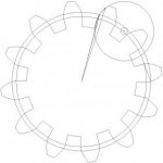
when i plotted the angular error of an involute (12 tooth, 20 degree pressure angle, no funny stuff) compared to a simple radius, the error is a minimum of about .09 degrees. just by eyeballing the matter i was able to get an error of .08 degrees and .1 degrees.
unnamed2.jpgunnamed21.jpg

so one problem is finding a creative way to flip the gear over while using the same hole for the radius generator so both sides of the gear are generated at the same radius. one option is drilling the indexing holes all the way through the gear blank. if they are small enough and located in the center of the tooth, the gear will not be weakened significantly. if the indexing holes are below the base circle the gear won't be weakened but the gear won't be as accurate because of the fixed error that you get from drilling a standard hole (no one has the time to drill and bore the indexing holes if we're only approximating the involute with a single damn radius)

you could dimple the gear teeth on the face of the gear on the end of the tooth and use a ball plunger to index each tooth.. but this will only work on larger gears bigger than mod 2 or 12 dp unless you can use tiny drills and tiny ball plungers.


a standard 8" diameter grinding wheel is probably good up to a gear of 1/2" thickness. above this, the grinding wheel is going to bottom out in the middle of the root between the teeth and this will weaken the gear, concentrating forces in the edges of the roots of the teeth.


another possibility is that you simply drill the root of the tooth with a drill bit, and use those holes as the index. put the dowel pin which fits into the root of the tooth blanks far enough away so it doesn't run into the grinding wheel.

Untitled.jpg
 
Thanks every one for sharing the alternative methods suggestions .
It's often nice to have more than one way to do things where we can choose a method that best suits our job at hand with the tools we have and our abilities .
 
Interesting video.
I have used a grinder to make and repair straight tooth gears and racks. Often first going through with a parting wheel.
Some I have used a good tooth for the template for wheel dressing, and finish up with a grease pencil or blue-in going from a good tooth to the repair one.
Using the existing teeth for the index is often good. on a repair job.
A TC grinder with having an index can also be handy.
Likely a spin index may also be good (have not done that way).


Back
Top