What's new
What's new

CVA Toolroom Lathe – Apron Rebuild

CarbideTip

Aluminum
Joined
Sep 21, 2016
Location
Woking, Surrey, UK.
Well it’s been sitting on the bench looking back at me for the last six months and now the time has come to see what needs doing.
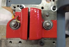
DSCF5650.jpg

There will be a good deal of commonality with a 10EE apron as the early CVAs were a clone of the round dial but with a conventional AC motor and gearbox. There will be some differences too. First off CVA’s don’t have the protective cover over the worm and wheel. I may try and add one to mine.

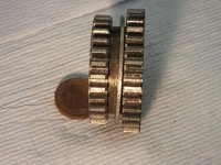
I’ve been aware for a while that my apron is in a poor state due, I believe to neglect rather than abuse of the previous owner. This is the oil window sighting disk (don’t think 10EE’s have these)

Oilwindow.jpg


The discolouring is almost certainly due to cutting fluid getting into the apron. Some of the others were slightly discoloured due to oil but this one is by far the worst of the 6 on the machine.

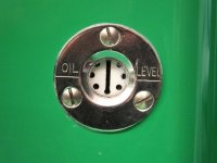
Here’s what they should look like (This is a head stock one. There's no oil in at the moment)
DSCF5950.jpg

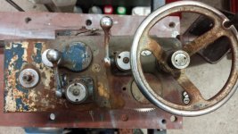
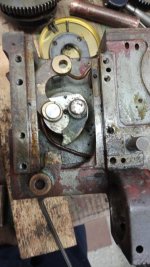
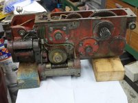
Dismantling was fairly straightforward, but everything inside the apron was very dirty.


DSCF5925.jpg

DSCF5934.jpg


I will be replacing all the ball races but the manufacturers choice of shielded vs unshielded seems a bit bizarre to me.

Worm wheel shaft: 2 x 6204 with double shields
Carriage traverse hand wheel shaft. 2 x 6203 unshielded
Rack pinion shaft. 2 x 6205 unshielded

Why not put a shielded bearing next to the rack pinion?
Similarly why is the worm wheel shaft shielded on the front of the apron where it’s covered in?
 
Well it’s been sitting on the bench looking back at me for the last six months and now the time has come to see what needs doing.

View attachment 342362

There will be a good deal of commonality with a 10EE apron as the early CVAs were a clone of the round dial but with a conventional AC motor and gearbox. There will be some differences too. First off CVA’s don’t have the protective cover over the worm and wheel. I may try and add one to mine.

I’ve been aware for a while that my apron is in a poor state due, I believe to neglect rather than abuse of the previous owner. This is the oil window sighting disk (don’t think 10EE’s have these)

View attachment 342363


The discolouring is almost certainly due to cutting fluid getting into the apron. Some of the others were slightly discoloured due to oil but this one is by far the worst of the 6 on the machine.

Here’s what they should look like (This is a head stock one. There's no oil in at the moment)

View attachment 342364

Dismantling was fairly straightforward, but everything inside the apron was very dirty.
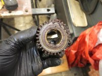

View attachment 342365

View attachment 342366


I will be replacing all the ball races but the manufacturers choice of shielded vs unshielded seems a bit bizarre to me.

Worm wheel shaft: 2 x 6204 with double shields
Carriage traverse hand wheel shaft. 2 x 6203 unshielded
Rack pinion shaft. 2 x 6205 unshielded

Why not put a shielded bearing next to the rack pinion?
Similarly why is the worm wheel shaft shielded on the front of the apron where it’s covered in?

It looks like the gears are ok but were neglected. The 10ee doesn't gave the two copper oil lines going to each worm gear bearing like your CVA. I like that!
Also like the oil level line stamped on the sight glass retaining ring..

Your question about the shielded bearing. I'm not a fan of shielded bearings where an oil supply or grease fittings are already there.
Your lathe may not see prolonged daily use and shielded bearings may be ok. But why?
If it's to prevent oil leaking you could buy a shielded bearing and pop the shield off of the side facing the oil. Then the outside would have a shield.
There are pin sized holes on the shield on most shielded bearings. I believe for venting.
With one side open you could add a little sealer to the outside shield being careful not to get it in the bearing.

I would make a shield like on the 10ee for the worm drive gears. An empty spam can:D
You can put in some hours rebuilding an apron.

Your question:
Similarly why is the worm wheel shaft shielded on the front of the apron where it’s covered in?
Someone else may have replaced it with shielded or to retain the oil. That doesn't make sense.

You need a CVA guru.

It's looking good. Enjoy your lathe.
 
Keep the pictures and posts coming. I am soon taking delivery of an earlier version ( square head but with clutch ) and also need advice. Pretty rare here in US. Dave
 
I’ve now cleaned all the components and have been trying to decide on the best way ahead. Cleaning started with scraping off the worst of the goo, followed by brushing in paraffin (kerosene) with an old tooth brush, followed by Evapo-Rust and ultrasound, followed by a scrub in warm water, followed by a wire wheel. This is the sliding double gear on the worm shaft (shown in the last post) which provides feed reversal.

DSCF5970.jpg

DSCF5967.jpg

This is the feed reverse 24T idler situated at the bottom of the apron:

DSCF5955.jpg

It has a bronze bush with an internal figure of eight groove groove for oil distribution (similar to those found in the feed gearbox bushes).

DSCF5958.jpg

Its shaft:

DSCF5978.jpg

The corroded section of the shaft is where it is exposed. The important surfaces are good. There appears to be very little wear in the shaft or the bush inside the gear.

Because of the pitted gear teeth I’m trying to find a source of replacements, although I’m sure that what I’ve got would probably be good enough. The teeth don’t appear to have much wear which makes it all the worse really. If they were pitted and badly worn the decision would be easy.

In the previous post I mentioned that the worm shaft used shielded bearings and I wondered if the 10EE was the same. I’m indebted to dinotom for sending me his list of round dial 10EE bearings. It seems that all the Monarch apron bearings are shielded. Otherwise CVA/Monarch bearings have the same ID and OD but differ in the width of the inner race. CVA seem to have used races with equal widths for the inner and outer race. Perhaps these are more readily available.
 
Up to eyeballs in tax season so CVA is still not here. The bearings should be fairly standard as it is the extended inner that is difficult to source . My other English machines are a mixture of metric and imperial so hoping the CVA is the former. Dave
 
Heads up yhe bearings are not easy
To source, they are standard angular contacts but the outer race of the front bearing is shortened by (straining my memory) .140" ir something similar. Or at least thats how my mk3 was.

I ground the outer race down on some fafnir replacements was a major mess around cleaning and reassembling.

Sent from my SM-G973F using Tapatalk
 
Is there any CVA literature that lists the bearings used? I have the manual from Tony that shows all three types but there isn't much in the way of parts diagrams or listings. Dave
 
Up to eyeballs in tax season so CVA is still not here. The bearings should be fairly standard as it is the extended inner that is difficult to source . My other English machines are a mixture of metric and imperial so hoping the CVA is the former. Dave

My experience so far is that CVAs also have a mixture of imperial and metric bearings. The feed gearbox was mostly metric, but the feed stub shaft were imperial.
Apron is all metric for ball races but the thrust races (3 in each of the clutches) are imperial.
 
Heads up yhe bearings are not easy
To source, they are standard angular contacts but the outer race of the front bearing is shortened by (straining my memory) .140" ir something similar. Or at least thats how my mk3 was.

I ground the outer race down on some fafnir replacements was a major mess around cleaning and reassembling.

Sent from my SM-G973F using Tapatalk

Angular contacts for the apron worm wheel shaft???
My post might have been misleading "worm shaft used shielded bearings" - I should have said worm wheel shaft.
What I removed were 6204 with double shields, but they were SKF where every other bearing I've found so far has been Hoffmann.
So maybe they have been changed previously.
 
Is there any CVA literature that lists the bearings used? I have the manual from Tony that shows all three types but there isn't much in the way of parts diagrams or listings. Dave

I have a list of what I've changed in mine. I will create a table and post here at some point.
The manuals from Tony don't show generic part numbers. Presumably so you had to go back to CVA for spares:(
 
Apologies for some reason i thought we were talking about the front spindle bearings. Please ignore my post and continue

Sent from my SM-G973F using Tapatalk
 
Another Apron

I went on a little trip today to collect this:

IMG_20220309_171328.jpg

It's a bit tatty outside but the internals look better than what came out of mine.
There's no sign of corrosion damage inside and it's all still wet with oil.

IMG_20220309_171516.jpg
 
..... The 10ee doesn't gave the two copper oil lines going to each worm gear bearing like your CVA. I like that! .....

Well now, here's the spare apron

DSCF5986.jpg

It only has one oil line to the worm bush!

It's not like it's just missing.
The holes are not there for it either in the oil well at the top of the apron or where it goes in to feed the bush.

I didn't get the serial number of the machine it came from so I don't know which is the later design.

How odd.
 
I have now stripped and cleaned all the parts from the ‘spare’ apron. Its a mixture of good and bad news! The apron has been repaired at least once and some parts have been replaced.
I will need to spend some time comparing the parts from both aprons to allow me to select the best bits. The spare is from s/n AH1085 mine is AH1311, so the spare is older. Probably 1958 or 1959. Mine is 1961.

I made a real hash of getting the feed reverse shifter fork out. It’s secured with a taper pin which is difficult to get at and I could not shift. My attempt to drill it out wandered off course and I now have a figure of 8 shaped hole in the shaft.

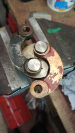
One interesting discovery was a broken half-nut actuator arm:
IMG-20220323-WA0005.jpg

Not only is this broken, but it looks like it has been repaired once before.
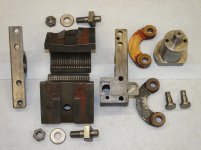
I won’t need these bits as at that time I believed that mine were OK. I mentioned it to the chap I got the spare apron from. He was surprised, but a few days later he sent me this picture of one of the spare parts that came with the machine when he got it.
Spares_thatcamewithit.jpg

After seeing this I looked at the lower half nut and the interlock that prevents the half nuts from being closed unless the feed reverse is in the neutral (centre) position. The interlock pin was a bit bent suggesting excessive force had been applied by an operator not familiar with the machine.
IMG-20220331-WA0002.jpg

Out of curiosity I re-assembled a few of the bits to see if the interlock worked as it should. It did, even with the bent interlock pin.

As hinted earlier, when I examined the parts from my machine I found that it too had been repaired, although whoever did it made a good job of it. So much so that I had not noticed when I took it to bits.
IMG-20220404-WA0007.jpg

I had a quick search here but I can’t see any reports of this breakage on 10ee’s. The 1942 10EE manual shows these parts as being bushed at the ends. Are the 10EE’s arms made of steel with bronze bushes? The CVA ones are bronze castings and don’t appear to have bushes.
Bronze or no I can’t help but feel these must take some breaking!
 
Since the current subtopic is threading and the half-nuts here’s CVA’s version dismantled:
DSCF6038.jpg

DSCF6040.jpg

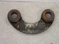
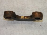
Because one of the arms has been repaired I checked to see if the hole centers were the same as the good one. They are not! I have a third arm from the spare apron…..different again :eek:

DSCF6042.jpg
DSCF6043.jpg
DSCF6044.jpg

Spare unbroken arm hole centers: 1.993”
From my lathe unbroken arm hole centers: 2.034”
From my lathe repaired arm hole centers: 2.083”

It looks like there is some adjustment as the holes in the half nuts are 7/16” and the half nut arm bolt is 3/8” diameter, but I would have expected these to made on a jig so the hole centers would be identical.

10EE Folks – Can anyone tell me what the hole center distance is on a 10EE?
 
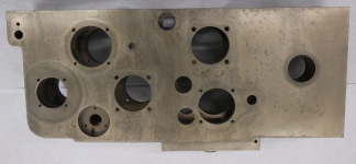
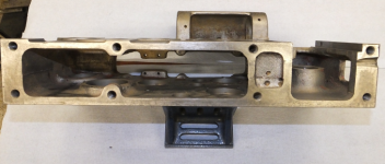
Back to the apron itself and with everything removed, I spent some time cleaning the internal cavity. There were places where the flashing had not been completely removed. A small stone on a flexi-shaft was used to remove these. I then had the casting bead blast cleaned.

1654123111572.png

1654123158823.png

1654123221492.png

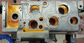
And applied some paint to the internal surfaces.

1654123325147.png

1654123389645.png
 
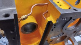
The first parts to go back were the oil pipes from the metering valve to the distribution well, and from the well to the upper half-nut slide.

The T piece had to be modified, as like the saddle oil system, I have replaced the original 1/8” BSP threaded metering units with current metric threaded equivalents. This was easy enough to do. I simply opened out the hole and made a brass bush with an M8 x 1 (ISO fine series) threaded hole and seat to accept the new metering unit. The bush was then silver soldered in.

DSCF6034_s.JPG

IMG_20220409_221202_s.jpg
With the modified T and the metering valve in place, the new oil feed pipe could be bent and fitted. I’m using 5/32” (4mm) copper pipe although the originals seem to be brass. The short pipe that feeds the half-nuts was a struggle. It took four attempts and still there is a kink in the bend. Despite the kink there is still a good size passage for what will only be a dribble of oil.

IMG_20220525_201234_s.jpg
 
Setting the half nuts.

At a first glance there does not appear to be any adjustment possible, but the pins that connect the half-nuts to the drive arms are 1/16” smaller than the holes. This gives some scope for setting the vertical position of the nuts so that they close uniformly on the leadscrew, even if the saddle is slighter lower due to bed/saddle wear.


HalfNut1.jpg

The main difficulty is accessing the securing nuts once the apron is in position, so whilst the apron was relatively light (no internals) I fixed it to the saddle and temporarily fitted the leadscrew. Again for access I have not fitted the two additional castings that house the threading dial and the apron control.

DSCF6128_s.jpg
To give better access to the nuts I did not use the cast retainers but just a few screws and washers


Secured.jpg

Then closing the half-nuts and lightly squeezing them together onto the leadscrew and tightening the two nuts. The top one is the more difficult and I had to grind some of the end of the spanner away to make it fit.

DSCF6131_annotated.jpg

With the nuts tightened the apron was removed ready for fitting the internal components.


Back
Top