What's new
What's new

CVA Toolroom Lathe – Apron Rebuild

Replacing the apron internals.

The order in which I took the apron apart wasn’t ideal. So for re-assembly I did some ‘dry runs’ first using dummy ‘bearings’ made from light alloy with clearance (rather than interference) fits. In essence it’s really quite simple. Start at the bottom and work up.

As I had removed the three steel bushings that locate the inboard end of the intermediate gear shafts, these went back first, but only the lowest two should be replaced at this point. When I dismantled the apron I used a depth mike to measure how much each bush was above or below the apron surface. These dimensions help to get the bush back in the same position and it wasn’t that hard to get the threads aligned and the grub screws replaced.

LowerBushes.jpg

The screws that secure these bushes and shafts are all 3BA x ¼” socket grub and (even in the UK) not as easy to source as they once were. Perhaps because I grew up using BA threads, they always look right to me. In this size metric looks too fine and UNC too coarse. #8 UNF is however pretty close. So close it nearly fits!

3BA is 0.1614” OD x 34.79 tpi (BA threads are defined in metric units) and 47½ degree thread angle!
#8 UNF is 0.164” OD x 36 tpi

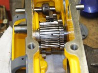
First to go back in is the worm-wheel shaft and the sliding gear with two SKF 6204 2Z ball races. These are shielded and identical to those originally fitted.

Next in is the feed reverse shifter fork and it’s control rod. The two aprons I dismantled were different in that the taper pins securing the fork were fitted in opposite directions. If you have to re-ream for an oversize taper pin, make the large end towards the top of the apron.

Then the feed reverse idler and the long compound gear that drives the two feed clutches. All of these gears came from the spare apron as they were in better condition but the shafts are my originals so that the securing grub screws would line up. The shafts are hardened BTW.
DSCF6148_s.jpg

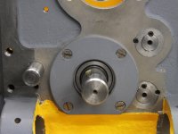
The inner cover can then be fitted, but the cut-out must be at the bottom otherwise the worm won’t fit. The cover screws are 3BA.

DSCF6155_s.jpg
The next shaft to fit is the apron hand-wheel with it’s gear and cam that actuates the oil pump.
The shaft runs on two standard 6203 bearings. I replaced like for like so these are unshielded. The spacer goes nearest the front of the apron.

DSCF6152_s.jpg

One difference to the 10EE is that the inner cover does not have a central hole, so the bearing is not exposed and does not need to be shielded.

Composite.jpg

(for the equivalent 10EE see second picture in Karl Sorensen’s excellent 1942 apron thread: https://www.practicalmachinist.com/forum/threads/42-round-dial-apron-assembly.385782/post-3684021)
 
Replacing the apron internals, continued.

Next to be refitted is the longitudinal feed clutch.
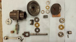
Here are the component parts with the original thrust bearings.

IMG_20220212_164055_s.jpg

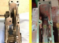
Unlike round dial10EE’s there is no need to put the large rack shaft gear in position before fitting the clutch. The apron castings differ significantly in this vicinity so it’s fine to put the clutch back at this stage.

CVA-10EE.jpg

The left image in this composite picture is from Karl Sorenson’s ‘42 round dial apron rebuild thread. The right image is my CVA.

It appears to me that there are some issues with the lubrication of these clutches, particularly the thrust race nearest the operator. In all four of the clutches I have dismantled this race was in worse condition than the others. The clutch housing does have an oil feed from the distribution reservoir, but it seems to me that the oil doesn’t reliably reach this race. After reading this post

https://www.practicalmachinist.com/...problematic-oiling-system.396554/post-3840808

and some consideration I decided to add a ball oiler in the flange of the casting. Conveniently, this is directly over the center of the thrust race.

The thrust races themselves are not common but are still available. In the composite image below the top two bearings were removed from the spare apron. By this time I had already sourced new ones to replace mine, but had I not done so I would have used some of those from the spare which must have been rebuilt at some point.

Composite.jpg

The lower two bearings came from my lathe. Clearly the larger one is in pretty bad shape. It was one of those from inside the clutch housing.

Large the large ones are LT½ and the small ones are FT½.
My originals were made by Hoffmann.
LT½ are 1/2” ID x 1-9/32” OD x 5/8” Wide.
The Hoffmann ones had solid brass cages but the replacements were pressed steel.
The raceways also differ. On the Hoffmann originals both races have a precise 1/2” bore, but on the replacements one is precise and the other has a clearance hole. Perhaps to allow the floating part to self align?

FT½ are 1/2” ID x 31/32” OD x 1/4” Wide. These are more difficult to source but seem to be available both in the UK and USA on ebay but of unknown (to me) quality. I managed to find some new, old stock made by RHP (Ransomes Hoffmann Pollard, an amalgamation of three older companies).

Are the 10EE ones dimensionally the same I wonder?

Here’s a trial assembly:

LongClutchAssyAnnotated.jpg
 
I discovered that a shim washer was needed to prevent the back face of the large clutch gear rubbing against the edge of the housing. I can not really explain why both long and cross feed clutches were like this, yet those from the spare apron were not. Because the gear had been rubbing there is a visible wear ring on its back face. What was surprising was the amount of extra effort required to turn the wormwheel, especially with both clutches rubbing. Perhaps there is wear in some of the clutch components, or perhaps it’s just a build up manufacturing tolerances. Something to look for if you’re rebuilding a CVA / 10EE apron.

Once assembled the oil feed pipe can be fitted whilst access is good. Here the original 5/32” OD brass pipe has been replaced with 5/32” copper.

DSCF6166_s.jpg
 
Continued from last post.

Next to be fitted is the clutch for the cross-feed. This is essentially the same procedure as for the longitudinal clutch, but there are two more oil feed pipes that need to be fitted into the well first. One will feed the clutch and the other feeds the shaft with the cross-feed idler on it. With these two pipes located in their well outlet holes the cross feed clutch can be fitted. Once in place the bush that supports the cross feed idler gear shaft can be fitted followed by the gear and shaft.

This shaft has an internal oil passage that feeds the gear bearing. On the spare apron the plug that blanks the drilled hole in the end of shaft was missing. Something to watch out for maybe.

BlankPlug.jpg

The oil pipes previously inserted into the well can now be bent to shape and pushed into their respective destinations.

The only shaft left to fit is the rack shaft. This runs on a pair of 6205 bearings. I used a shielded bearing adjacent to the rack gear to help keep swarf out, but the originals were unshielded. There’s a bearing retainer to fit and tighten then the front and rear covers can be fitted with yet more 3BA countersunk screws.

Pipes.jpg


There is very little clearance between the cross-feed clutch gears and the pipe that feeds the idler shaft, nor is there much height difference between the well and the shaft. I wonder how effective it is. This pipe is the only original oil pipe I've used. It's brass hence the color difference.
 
With all the shafts and gears in place the next thing to go back is the oil pump.
Well perhaps ‘back’ is the wrong word since mine had no oil pump at all when I received it.
At some point in it’s previous life the pump had been removed. Because the apron had suffered coolant damage it may be that the pump had seized and prevented the carriage from moving. It is impossible to tell how long the pump had been missing and what damage had resulted from lack of lubrication, but as soon as I was aware I started looking for a replacement.

First chance came from a 1953 Mk1A series 2 lathe that was being scrapped. It turned out to be an very poor condition, and although it could have been repaired I later managed to get another, in good condition and from a series 3. I messed up here because I subsequently bought the rest of the apron that it came from to replace some of my corroded gears. It would have been better to buy the whole apron in the first place.

PumpsCompared.jpg

In this image the top pump is the later one. Clearly the two are somewhat different.

Early pumps seem similar to the Bijur fitted to 10EEs. The inlet is at the end and the outlet on top.

Later pumps have the inlet underneath and the outlet on the end. This makes it easier to undo the delivery pipe union when the pump is in situ. The ram is much bigger in the later style. ¼” against 5/32”. One thing to note about these pumps is that the delivery pressure is determined by the ram diameter and the spring stiffness. The delivery pressure does not come directly from the cam action. The cam merely draws the ram back to charge the pump with oil. 10EE Bijur pumps are the same in this respect.

Both versions of the pump fit on the same mounting holes and are secured by four 2BA socket head screws. The delivery pipe connection is 1/8” x 28 BSP.
The later style dismantled:
PumpDiss.jpg

The early pump had both gauze and felt filters on the inlet. The later only has a gauze held in by a circlip. At first I thought this must have been a botch as there is no groove for the circlip.

NewPumpInlet.jpg

On checking the CVA parts manual it appears that this was what was intended. I wasn’t happy with the arrangement and decided to make a press fit insert with a soldered in gauze. Because of the limited clearance between the bottom of the pump and the sump the filter had to be as thin as possible. The original gauze seems to have 60 holes per inch on both directions.

One disadvantage of having the inlet on the bottom is that the pump will pick up whatever is at the lowest point…..water/coolant/sludge etc. I will be draining mine on a routine basis!

NewFilter.jpg

With the apron upside down the pump can be fitted and delivery pipe connected. I made a new pipe for mine but this must be done before the half-nuts are installed.


PumpInSitu.jpg
 
Great timing. The apron and oil change for my CVA is coming up shortly. The pump still works and both ways are getting oil so my desire to make better and possibly make worse is low. I'm guessing I will have the earlier version of the pump/ Dave
 
Great timing. The apron and oil change for my CVA is coming up shortly. The pump still works and both ways are getting oil so my desire to make better and possibly make worse is low. I'm guessing I will have the earlier version of the pump/ Dave
Yes, I would think you'll have the earlier type of pump.
I do wonder if the earliest CVAs were fitted with Bijur lubrication. Let us know what you find.
 
The delivery pipe from the pump goes to a T piece. On CVA's this is held on by a single screw at an odd angle. For testing I have temporarily blanked the outlet that will eventually go to the saddle.

Tpieceinsitu.jpg

With the pump and pipe in place the apron sump can be fitted. I made a gasket although there wasn’t one on mine when I got it. The fixings are 2BA socket cap screws. I shortened one of them as it enters the pocket for the oil window and might upset the sealing.

OilWindowAperture.jpg

Some time ago I made up some simple press tools to cut new cork seals for the oil sight windows. I also made a new batch of sighting disks. The cork is 1/16” thick. The original windows are 2mm glass.

Here are the bits in assembly order:

Assy.jpg

The parts in the picture are all spares. I realized too late that I had not taken a picture of mine prior to assembly.

The assembly process is tricky. I used just a smear of sealant on all the cork parts. If you put too much on it squeezes out and obstructs the window when the screws are tightened. These are 3BA raised head countersunk. The originals were black finished, but the heads were a bit chewed and I replaced them with stainless steel.

Later machines and those that have been rebuilt have often had these sight glasses replaced by press fit ones. I think sealing them, and keeping them oil tight can be troublesome.


Apron_Left.jpg
 
With the oil pipes completed the half-nuts can be fitted.
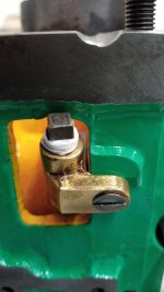
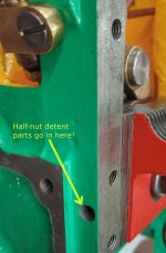
Reassembly is very straightforward but don’t forget the two sprung detents. One for the half nuts and one for the feed reverse plunger.

Arms.jpg

Detent.jpg

Complete.jpg

On the front of the apron there’s a chromed bezel and operating lever secured with a taper pin.
Mine was sloppy and I had to ream slightly and cut a new taper pin to suit. The taper pins on mine have all been the imperial standard of 1 in 48 (1/4” per foot).

Lever.jpg
 
The power feed drive on CVA’s looks to be a bit different to that on 10EE’s.
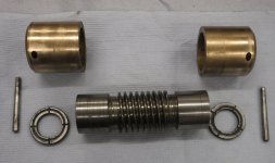
Here are the parts:

Worm1.jpg

There are no ball thrust races, just two steel thrust rings which fit inside the bronze bushes. One side bears on the end of the worm the other on a shoulder in the bush. The bushes are press fitted into the apron casting and are secured by long taper pins which pass through the apron casting and the edge of the bush. The worm itself has a bearing surface on either side of the helix. These run in the bushes.

The two thrust rings have oil grooves and there is an oil feed pipe into each bush right over the ring.

For most turning operations where power feed is used, the thrust on the worm is towards the headstock. (feed reverse is implemented in the apron) So it was no surprise that the thrust ring on this side of worm was much more worn than the other.

Thrusts1.jpg

The picture shows both sides of each ring. Top and bottom images on the right are of the ring nearest the headstock. The oil groove on one side has almost worn away and there are further signs of coolant related corrosion that has been a ‘feature’ of this machine.

I had intended to make new bronze bushes but as I have not had a bed re-grind and built the saddle back up, the apron will be lower than originally. This means that new bushes would need to be bored slightly off center and fitted in the correct orientation which I felt would be too difficult. As the play in the old bushes was not excessive I decided to keep them, but to skim the ends of the worm and make new thrust rings.

The worm is worn and that from my ‘spare’ looked a lot better until I looked down the bore. The key was quite thin so I’ll be using my original part.

The key appears to be the full length of the worm but only the central third (that’s a guess) engages with the slot on the feed shaft. The remaining two thirds have been machined away.

Does anyone know how these keys are fitted?
Are they replaceable?

I could just about convince myself I could see a braze or silver solder line but I’m really not sure.


Worm2.jpg

The ends of the worm didn’t take much cleaning up. Perhaps 5 thou each end. Using the old thrust rings I reassembled it and put the taper pins in. I set up a DTI to measure the worm end float. Using this figure and the thickness of the old rings I made the thickness of the new ones to so that the end float was between 5 and 10 thou. It might have been easier to make the rings first and skim the ends of the worm to get the right clearance.
The new rings:
RingsNew.jpg
Assembly is fairly straightforward and I should admit that it was done before the apron oil pump and sump were fitted. (The sump obstructs one of the taper pins that hold the bushes in).

There are a couple of points to note though. Firstly, the worm shaft bearing cover has a flat which must be at the bottom otherwise the worm will not fit and second, the worm wheel must be fitted before the worm.

Worm3.jpg
 
On 10EEs, keys like that are usually "tit keys". They have a little pin in the middle that engages a hole in the middle of the keyway. Look carefully at the outside of the worm and see if you can see the hole, probably in the root of the thread.

Although, IIRC the worm for 10EEs appears to be machined/broached into the worm. If that's the case, it would be a very interesting machining operation.

Cal
 
Thanks Cal.
The CVA has a lot of those 'tit-keys' too, and the parts manual refers to them using that exact term.
In the case of the worm I could not see any evidence of the 'tit'.
The parts manual does list it as a separate item - 'key' - which suggests that it is removable and was available as a spare.
When I get some spare time I will try and remove the key from the spare. If I can make and fit a replacement key it would be worth swapping them over.


Back
Top