What's new
What's new

Deckel FP1 vertical spindle brass bushing oiling point

I am not sure now, but if it's got movement, then I don't think lapping and removing more material will help. Since material cannot be added, I think a replacement bronze sleeve is required.
 
Funny - the last line in that thread is about adjusting the spindle nuts to improve runout. I did this last night and am now just under one thousandth of an inch runout (by hand and under power). Clearly tighter is better for runout. There are several posts about tightening these nuts for the needle bearing spindle as “finger tighten plus a little”. Is the same true for the bronze bushing? I ran the spindle at this adjustment for about 10 minutes without noticeable heat on the spindle.

In a perfect world the bronze would be just plastic enough to allow me to incrementally tighten the spindle nuts over time and improve runout, but this might be wishful thinking.

The good news is that the quill fits the housing very well and I have the new oiling tube installed.

Thanks again,
John
 
Since material cannot be added, I think a replacement bronze sleeve is required.

Not sure this is exactly true.....Believe since the spindle and the bearing sleeve are tapered, that one can tighten the radial clearance between the bushing and shaft(spindle) by
moving the spindle axially. Believe there is a procedure in the FP1 manual for this....Requires precision surface grinding of the spacer and testing for fit.

The caution here is that you need to make adjustments carefully. Reduction in the spacer length will tighten the clearance,if you go too far then you will have to make a new spacer and start over.

attachment.php


Cheers Ross
 
The good news is that the quill fits the housing very well and I have the new oiling tube installed.

Photos please, they will help the next person in this situation.

Important: are you talking about "runout" which means that the spindle does not run true? Or are you talking about "free play" which means that you can shift the spindle position radially or axially?

I always thought that one advantage of journal bearings was that you could adjust them with shims or spacers to reduce the play to the correct amount. On my Studer cylindrical grinder, the wheel head has a solid bronze journal bearing. The procedure to adjust it is to rotate two locking nuts until there is 50 microns (about 0.002") of end play in the spindle. The bearing taper is 1:10 so this yields 5 microns (0.0002") of radial play when dry. With oil and running at speed that free play is eliminated.

You can not eliminate runout this way (runout indicates a non-cylindrically-symmetric spindle shaft). But you should be able to adjust out the free play (or reduce it to the correct amount).

EDIT: I see that Ross has just posted the page with the correct procedure for adjusting the free play.
 
Not sure this is exactly true.....Believe since the spindle and the bearing sleeve are tapered, that one can tighten the radial clearance between the bushing and shaft(spindle) by
moving the spindle axially. Believe there is a procedure in the FP1 manual for this....Requires precision surface grinding of the spacer and testing for fit.

The caution here is that you need to make adjustments carefully. Reduction in the spacer length will tighten the clearance,if you go too far then you will have to make a new spacer and start over.

attachment.php


Cheers Ross

Ooh I missed that it was tapered.
 
After several adjustments to the spindle nuts the runout is close to spec! I guess bronze bushings are as forgiving as I have read.

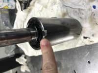
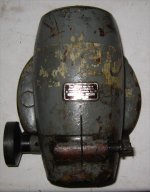
A note to anyone who might find themselves in this position in the future. There isn’t enough clearance between the quill and the horizontal spindle drive gear so I needed to notch the quill at the top front to allow the addition of an oiling tube. It’s strange that the photo earlier in this post of another quill with Bronze bushing shows this notch, but mine doesn’t.
35602909-1D1B-4E90-A733-6B712C42D6FE.jpg

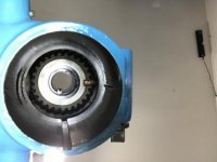
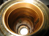
Once this is added the location of the tube is pretty obvious. I used 1/4” copper tube which can bend for initial fitting. Here is a photo looking up into the housing with the quill removed.
35602909-1D1B-4E90-A733-6B712C42D6FE.jpg

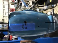
Lastly, here is the hole for the oiling tube. Measurement is from the flat top of housing.
4C6BAB8F-A8D3-4440-A535-0D55C2ED9DC6.jpg

Thanks again for all the help!
John
 
After several adjustments to the spindle nuts the runout is close to spec! I guess bronze bushings are as forgiving as I have read.

A note to anyone who might find themselves in this position in the future. There isn’t enough clearance between the quill and the horizontal spindle drive gear so I needed to notch the quill at the top front to allow the addition of an oiling tube. It’s strange that the photo earlier in this post of another quill with Bronze bushing shows this notch, but mine doesn’t.
View attachment 279523

Once this is added the location of the tube is pretty obvious. I used 1/4” copper tube which can bend for initial fitting. Here is a photo looking up into the housing with the quill removed.
1D454665-19C5-46D7-A656-26B17EACE75D.jpg

Lastly, here is the hole for the oiling tube. Measurement is from the flat top of housing.
View attachment 279524

Thanks again for all the help!
John
 
Hi John,

Glad you were able to adjust the tapered bearing to get the free play down to the recommended value. Thanks also for the photos of the oil tube -- they will help the next people with this problem.

Cheers,
Bruce

PS: I suggest that you delete post #47, since it's a duplicate of the following post but the second picture is missing.
 
After several adjustments to the spindle nuts the runout is close to spec! I guess bronze bushings are as forgiving as I have read.

A note to anyone who might find themselves in this position in the future. There isn’t enough clearance between the quill and the horizontal spindle drive gear so I needed to notch the quill at the top front to allow the addition of an oiling tube. It’s strange that the photo earlier in this post of another quill with Bronze bushing shows this notch, but mine doesn’t.
View attachment 279523

Once this is added the location of the tube is pretty obvious. I used 1/4” copper tube which can bend for initial fitting. Here is a photo looking up into the housing with the quill removed.
View attachment 279523

Lastly, here is the hole for the oiling tube. Measurement is from the flat top of housing.
View attachment 279524

Thanks again for all the help!
John
I,m a little bit late to the party but pretty well versed in regard to the differences in the FP1 heads. They came in both versions with the bronze bushing, with and without the flip top oil port. The later one without is lubricated through the slot for the drive key which will also oil the drive gears. In my opinion the ideal setup, none of the other early heads account for getting oil to those gears. I have several different heads with the 4 Morse taper including one off a dual dial machine and on all those I never saw a single mention to lubricating the gearing in any of my manuals?
Dan
 
1955 FP1 head rebuild

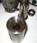
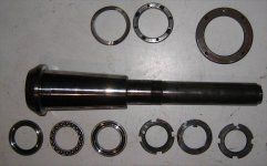
Am in the middle of rebuilding my ~1955 FP1 vertical head. Machine came out of a local city college, through a sales agent. Serial number on the vertical head is 31815.

Spindle bearing is bronze cone. Two areas for oil from the top, one marked on the bearing retaining nut and one through the keyway on the shaft. No provisions for cup oiler.


Img_8879.jpgIMG_8905.jpgImg_8895.jpgImg_8890.jpg
 

Attachments

  • IMG_8901.jpg
    IMG_8901.jpg
    86.7 KB · Views: 39
The bronze cone has felts at various heights to oil the surface. As verified with brake clean, there is a cavity between the brass cone and the steel to allow oil to wick down from the thrust bearings and replenish the felts.

Having been packed with grease, the felts are no longer capable of transferring oil cleanly.

I believe that this configuration was as supplied from the factory rather than being retrofitted.

IMG_8900.jpgIMG_8902.jpgIMG_8901.jpgImg_8899.jpg
 
Thank you for the great pictures1 My 1950's FP-1 has vertical head #35735. It was a "garage queen" for at least the last forty years so I am going to leave it alone and oil in the required areas.
 
The head casting was completely taken down and washed to remove all residual grease and contaminants. Slotted cuts had lots of foreign matter that needed to be removed. All components were washed to remove grease, with special attention to the bearings. No abnormal wear was seen.

The drive gears, while greased, were also taken down and cleaned in the ultrasonic tank. Tooth wear is normal and acceptable. Parts were oiled and reinstalled.
IMG_8913.jpgIMG_8914.jpg

Reassembly of the head casting consists of oiling all components and putting back into place. The drive gear assembly moves quite smoothly now.
IMG_8908.jpgIMG_8916.jpg
 
I’m glad this conversation cleared this question up. In retrospect I guess the oiling cup is a bit redundant, which isn’t a bad thing in this case.


Back
Top