I've seen a fabbed drive setup for rotating something large at slow speeds where they lasered a bunch of holes near the edge and welded in pins at the pitch of large chain. Then they used a chain sprocket to drive the pins. Not a great setup, but it worked and there was no machining in it.
How to install the app on iOS
Follow along with the video below to see how to install our site as a web app on your home screen.
Note: This feature may not be available in some browsers.
Largest Manufacturing Technology Community on the Web
Stay Connected:
You are using an out of date browser. It may not display this or other websites correctly.
You should upgrade or use an alternative browser.
You should upgrade or use an alternative browser.
Designing a horizontal bandsaw from the ground up
- Thread starter Halcyon
- Start date
- Replies 83
- Views 4,457
RC Mech
Stainless
- Joined
- Jul 21, 2014
- Location
- Ontario, Canada
A shitty is such a horrible thing to use. I'd hate to see someone waste so much time and money building the worst bandsaw ever.
A shitty what? A shitty WHAT? I’m waiting here with baited breath.

The OP should use a Carolina bandsaw for 1 year. Then he’ll see what he’s in for with this design.
Lol Carolina!!!
My FIL needed a new bandsaw for his hobby shop- He wore out his HF bandsaw. I warned him about Carolina. Told him about one I bought for $200 and sold for $50 and all the things wrong with the design. 2 years goes by and he calls me all excited. He bought an "Industrial Bandsaw"!!!!
It's brand new! Carolina still makes them! He tells me the new ones are way better. Oh boy. I see it and it's the same exact pile of shit except it's green instead of red.
memphisjed
Titanium
- Joined
- Jan 21, 2019
- Location
- Memphis
Spend a few months with a real saw before trying to design a saw. If you have not used one not sure how you would even know what a saw is supposed to do and how it does it.
This isn’t saying a saw has to be multi ton weight class, they do not. By the time you start to price out gears, bearings, tension contraption, wheels, motors, drives... you still have money left, good because you still have frames, table, vices, wires, and you want a chip brush now too? Oh, coolant, so now coolant sump, pre pump filter, lines and nozzles. What psi should coolant be, what can you get away with?
What is your table made out of? Can it take the torsional loads the saw generates on a miter cut?
Alright, so some background.
What happened to #2?
Anyway, in light of #3, have you considered taking a used manual saw and turning it into an auto saw? That would make more a more interesting project, IMHO.
That's a cool idea!
To answer your question, the #2 went hypersonic.
It
That sounds like some burningman stuff! On that note I saw someone make a rack and pinion gear by welding a bike chain to a piece of tube straight and driving it a sprocket.I've seen a fabbed drive setup for rotating something large at slow speeds where they lasered a bunch of holes near the edge and welded in pins at the pitch of large chain. Then they used a chain sprocket to drive the pins. Not a great setup, but it worked and there was no machining in it.
Spend a few months with a real saw before trying to design a saw. If you have not used one not sure how you would even know what a saw is supposed to do and how it does it.
This isn’t saying a saw has to be multi ton weight class, they do not. By the time you start to price out gears, bearings, tension contraption, wheels, motors, drives... you still have money left, good because you still have frames, table, vices, wires, and you want a chip brush now too? Oh, coolant, so now coolant sump, pre pump filter, lines and nozzles. What psi should coolant be, what can you get away with?
What is your table made out of? Can it take the torsional loads the saw generates on a miter cut?
I've used quite a few band saws. Portabands, HF specials, the "nice" 12" Jets, and an Ellis. I've seen some very functional homebuilds.
So I did a bunch of editing. Made the cut envelope smaller, different geometry, ribbed things out, scapped the timing belt idea, and went with real bearings.


Last edited:
memphisjed
Titanium
- Joined
- Jan 21, 2019
- Location
- Memphis
None of the saws you mentioned are in the class of saws I am talking about. There is a big difference.
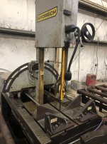
The vw is underbuilt, the v18 hydmech makes is the gold standard of steel to size ratio.
The vw is underbuilt, the v18 hydmech makes is the gold standard of steel to size ratio.
Attachments


memphisjed
Titanium
- Joined
- Jan 21, 2019
- Location
- Memphis
Your saw frame is still light. You can move motor drive to front wheel to reduce running tension stresses. Your tension wheel has to be in a rigid plane as it is pushed and pulled with varied work load. It works really well for reducing hp and frame twist- really bad if tension wheel has any play.
memphisjed
Titanium
- Joined
- Jan 21, 2019
- Location
- Memphis
That few hundred foot pounds at your hinge does not magically disappear at the hinge- your lower frame has to dissipate that.
moonlight machine
Diamond
- Joined
- Nov 19, 2007
- Location
- marysville ohio
Why don't you reinvent the wheel.
memphisjed
Titanium
- Joined
- Jan 21, 2019
- Location
- Memphis
Um, no comment.....idk how all that got into my notebook and computer.Why don't you reinvent the wheel.
Clean sheet design means clean sheet. I can see no advantage to the scissor design other than it is what people think a saw shape is. Lots of potential left on the table and a difficult joint to brain work.
None of the saws you mentioned are in the class of saws I am talking about. There is a big difference.
The vw is underbuilt, the v18 hydmech makes is the gold standard of steel to size ratio.
Those are wicked saws.
That few hundred foot pounds at your hinge does not magically disappear at the hinge- your lower frame has to dissipate that.
This is a 1000lb bearing load at the pivot. Should I instead be doing a moment load? Or does it matter in this scenario?


john.k
Diamond
- Joined
- Dec 21, 2012
- Location
- Brisbane Qld Australia
As for racks made from chain .....I made a machine with 40 ft of 3/4" pitch chain ,not welded ,but attached by pins either end,and driven by a weighted sprocket on a reduction box......if the drive collided ,the sprocket simply lifted and rolled over the chain..........professional engineers knocked this and that on the thing.......but time was run out ,so it was used as is ......It earned Col $2 million profit in two years .....and not a thing was altered..............Tyco got sick of Cols antics and cheating ,cancelled the contract,and the Tyco engineers built their own version......It jammed up with bitumen paint every few hours ,and had to be completely redesigned to be just like mine......anyhoo,dont matter now ,as Tyco moved production to China ........I was expecting a big bonus for designing and building the machines for the Tyco contract .....and got nothing ...zero .
memphisjed
Titanium
- Joined
- Jan 21, 2019
- Location
- Memphis
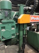
Of those saw: pedinghaus is a copy of Amanda Chinese saw- with exceptional build quality- poor engineering, ok design, controller is almost - almost - mach3 level (beckenhoff). Programming/hmi was designed by committee of engineers.
Hydmech- good build, good design, passable plc. engineering was left to simulation and the saw desperately needs another ton of metal kinda everywhere. And a bigger motor.... potential left off by bean counters.
The hem- classic American design. Big heavy and bold. Not the best build quality or tricky design. Very Thoughtful design for a saw, and when in doubt went bigger. If it had better vices and hydraulics I would rate it better. Best out of all the above saws- Still a little light on the ponies. It is manual, no plc.
Ries
Diamond
- Joined
- Mar 15, 2004
- Location
- Edison Washington USA
I run 1hp motors on my little 4x6 bandsaws, with a half inch blade. 1 1/2hp would be better...
Of course, they are much more rigid than what you are designing, being mostly cast iron.
I do have a 1" blade bandsaw, which is something like 3hp, and weighs around 1200 pounds.
It could definitely be more massive and have a bigger motor, too.
I once built a 16" bandsaw from plywood, with cast aluminum wheels. The 3/4" plywood box structure was more rigid and vibration resistant than the thin plate you are talking about, and it was still way too wiggly.
The basic idea would work, but I would go up to 3/4" plate, 5hp motor, and something like a yard of concrete cast into the base. And yes, you absolutely have to machine the wheels, which should, together, probably weigh about half what you are thinking for this entire saw.
I dont get the point. This is furniture design, not usuable tool design.
Scottl
Diamond
- Joined
- Nov 3, 2013
- Location
- Eastern Massachusetts, USA
For the work you are describing most people would seek out a used older USA made Porter Cable Portaband and make a stand with downfeed, limit switches etc. I have one of the old 2-speed models and it will cut 4 x 4 solid steel with the right blade.Noted
Fair enough. Just thought you might have access to some good reference material re the belt loading.
I cannot laser cut a pillow block out of plate. I looked into Cooks, it seems the smallest wheel they sell is 19".
Accounting for adjustability with possible heat distortion.
Noted
I'm going to seriously consider dropping to a smaller blade.
I figured 20ksi/700lbs at the wheel axles. Not sure if that's a sane number or not.
View attachment 388178
Should I bump them back up to 14"? Or larger?
My understanding of pulley and belt systems is poor. I thought it'd be a neat alternative to a gearbox since the pulleys could be laser cut, and worth exploring at least. The belt in question here is a 25mm T10. Does this seem more sane? The 30ft-lb figure is entirely arbitrary.
View attachment 388181
Do you think it's even tenable to build the wheel like this?
Yeah it's something I came up with after 3 or 4 bourbons. I guess what I really want is potentiometer controlled downfeed and automatic return. I like programming so it'd be something to keep me entertained for a bit.
It's a fun project to keep me occupied following a surgery. I don't forsee this getting heavy industrial use cutting billets and i-beams. Rather hobby/light professional usage for cutting tubing.
I think it'd be amazing if anyone could download the plans, have their local laser shop cut out the parts, and have a reasonably accurate and affordable mitering saw. Plus each machine built here means less $$$ funneled to the communists. Fight communism with communism! Also buy war bonds.
Not to dump on your project but a DIY wood cutting bandsaw is one thing whereas IMO your design is too elaborate for the average "maker".
And I 100% agree with DDoug that It is often far easier to imagine something in CAD or on paper than to actually build it.
I'm not usually one to be the voice of patience here, but I think the dumping has gotten out of hand.
We complain that nobody makes tools here anymore, and then when someone wants to start noodling in that direction, we shit all over it. He's working on it, he's improving the design, he's listening and learning.
Maybe we ease up on the "this is pointless crap" talk? Worst case, he learns how not to make a band saw.
But really, you do need machined wheels.
memphisjed
Titanium
- Joined
- Jan 21, 2019
- Location
- Memphis
I think a 3/4 inch vertical (rollin size) and small horizontal would be better made out a wooden beam design. Not the whole saw, the saw frame back out of laminated oak. Strong and has vibration dampening. Not a box frame, solid oak. Also would have better torsion resistance than smaller saws tend to have. If you really got into the design you could get tensioning with frame flex and cables.The 3/4" plywood box structure was more rigid and vibration resistant than the thin plate you are talking about, and it was still way too wiggly.
And yes, you absolutely have to machine the wheels.
Said before, say again: buy the wheels finished- machined/balanced and made out of cast iron. The commercial wood saw wheels are plenty stout enough for this level of saw.
Comatose: agreed, I do want not op to waste money thinking design is anywhere near ready. At the same time understand that semi functional saws exist for less than bearings, motor, wheels are going to cost him. That leaves making a better saw for a price point he must accept and is outside what the open source/ maker community wants to accept.
From machined wheels to press bearings, op has a lot of things to address in details. And the frame, and sub frame...vice...
I think it is worthy; a saw is an extremely complicated machine- a lathe is easier and cheaper to prototype out.
Automating an existing saw is more what he shows ability at. A portaband on trick tools stand with the old marvel dial feed? Or a Klucth horizontal frankenfeed... btw the Klucth is a good canvas to start with.
How many people on this site have bought a brand new saw? How many would get a new Marvel for msrp of 70,000? Or is down to 67?
Moving down to rollin/Ellis at 6-7g, which is reasonable material wise and some scaling of build numbers.
The jets/delta 6x for sub 3 to sub 1 for the 4x saw (my soft spot saw size and design). Which most people laugh at here- I say price to chip ratio the best of all.
The basic idea would work, but I would go up to 3/4" plate, 5hp motor, and something like a yard of concrete cast into the base. And yes, you absolutely have to machine the wheels, which should, together, probably weigh about half what you are thinking for this entire saw.
I dont get the point. This is furniture design, not usuable tool design.
Using the Ellis 1600 as an example; Has a total weight of about 520lbs(counting drive unit), has a frame pretty similar to what I'm doing(1/4 or 3/16" angle perimeter over plate, with addition of some flatbar along the spine), pushes a 1" blade with a 1hp motor, and cuts pretty well. The cast Chinesium saws that you reference are even less substantial than that.
I'll take your plywood and concrete suggestion into consideration if I'm feeling like I'm in a Bob Vila kind of mood.
Just because you can doodle it on your CAD....don't mean you should build it.
Recall the engine "Designer" that was here a few years ago ?
Oh man you've got to see some of my other projects.

I'm not usually one to be the voice of patience here, but I think the dumping has gotten out of hand.
We complain that nobody makes tools here anymore, and then when someone wants to start noodling in that direction, we shit all over it. He's working on it, he's improving the design, he's listening and learning.
Maybe we ease up on the "this is pointless crap" talk? Worst case, he learns how not to make a band saw.
But really, you do need machined wheels.
Thanks. Yeah, I certainly anticipated these types of replies. This is the internet, afterall. I actually just had surgery and ended up selling my Ellis, among other stuff. This is something I'm doing to maintain what little is left of my sanity. I definitely appreciate the more constructive replies, even if they're blunt.
My fiber laser guy assures me he can hold +/- 0.001" on smaller parts. Is that adequate for the wheels if one were to do crowned urethane tires over the flat geometry? Or does it absolutely positively have to be balanced and machined? Im just not ready to give up on them just yet.
I ran static loading sims and observed about 1/16" of lateral deflection over the length of the head. There's a simple technique I've used building ramps, and that's using the weld stress and fixturing to create a precise camber. One could "pre-load" the saw head the anticipated amount. Or integrate something like a guitar neck truss rod. Going to explore this further.
But maybe it's more the dynamic stresses that get you, I don't know. It seems like maintaining planarity between the blade wheels is the most crucial aspect to getting good tracking.
For the work you are describing most people would seek out a used older USA made Porter Cable Portaband and make a stand with downfeed, limit switches etc. I have one of the old 2-speed models and it will cut 4 x 4 solid steel with the right blade.
Not to dump on your project but a DIY wood cutting bandsaw is one thing whereas IMO your design is too elaborate for the average "maker".
And I 100% agree with DDoug that It is often far easier to imagine something in CAD or on paper than to actually build it.
I like the idea of a motorized portaband stand. It's actually a pretty cool and attainable thing. I agree, the average maker doesn't have a laser cutter. Final assembly would be within the purview of a decently handy person, ideally.
I think a 3/4 inch vertical (rollin size) and small horizontal would be better made out a wooden beam design. Not the whole saw, the saw frame back out of laminated oak. Strong and has vibration dampening. Not a box frame, solid oak. Also would have better torsion resistance than smaller saws tend to have. If you really got into the design you could get tensioning with frame flex and cables.
Said before, say again: buy the wheels finished- machined/balanced and made out of cast iron. The commercial wood saw wheels are plenty stout enough for this level of saw.
From machined wheels to press bearings, op has a lot of things to address in details. And the frame, and sub frame...vice...
I think it is worthy; a saw is an extremely complicated machine- a lathe is easier and cheaper to prototype out.
Automating an existing saw is more what he shows ability at. A portaband on trick tools stand with the old marvel dial feed? Or a Klucth horizontal frankenfeed... btw the Klucth is a good canvas to start with.
That's an interesting thought. An Oak tool in a welding shop might be frowned upon though. xD
I have scrapped the pillowblock idea once I talked to my laser guy. He says his laser can hold 0.001" on smaller parts, which makes me think that transition fit tolerances are attainable. I do like the idea of using tensile cables or rods.
I don't think I'll do a vise at all. Thinking rather a backing plate with slots cut to accommodate a stronghand clamp(less frame stress this way). Can rapidly reposition and clamp wide variety of stuff, and it doesn't impart as much stress on the platen/subframe as a vise.
This design would necessitate laser cutting, so I anticipate around $500 there. $500 for the plate. $500 for chibay gearbox and motor. Probably $200 in bearings and misc hardware. Full day of welding and assy time. Nice options: $300 for powdercoat, $100 for a VFD.
I think the other question is, who is this for? There's a few hundred dollars in bending at least in your sketch as well. Most Maker types don't have multi-hundred-ton cnc press brakes either. Once you add hardware, you're up north of $2000, probably closer to 3 once you get everything ironed out. You still don't have a downfeed system in the cost estimate above. Plus you have to make it. For whom, other than yourself, is spending $3k and another $2k worth of time going to be better than just buying a $5k used bandsaw on ebay? $5k buys a LOT of used bandsaw.
Why the resistance to machining your wheels? Do you not have access to a mill (manual or cnc) or a lathe? Even if your laser guy can hit .001 on small parts, once multiple pieces are aligned and welded, it's not going to be that perfect.
If you want internet maker acclaim forever, make a cnc auto-feed system for the ubiquitous 4x6 bandsaws, and make all the parts 3d printable.
Similar threads
- Replies
- 11
- Views
- 247
- Replies
- 4
- Views
- 676
- Replies
- 5
- Views
- 317