What's new
What's new

DoAll Vertical Band Saw Pusher

M.B. Naegle

Diamond
Joined
Feb 7, 2011
Location
Conroe, TX USA
Does anyone know of another place to buy the DoAll style work holding/pushing jaw? DoAll sells it new which I'd love to buy-

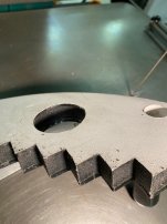
5-013007 - WORK HOLDING JAW

-But $410 for something that's mildly expendable seems a bit much, and it's on back-order. I'd like to stick with the DoAll style as it's made to work with the chain auto-feed system. Mine is missing some parts but on my list to re-create.

Anyone selling lazer-cut replacement jaws of the same profile, or have a DWG file they want to share that could go towards having some cut out? Would there be any interest in having multiples made (I don't think it's a patented design?) Did see this old thread (Building a DoAll Work Holding Jaw), but curious if making it on the same saw it would be used on is the only option?
 
I'd think you could make it a tad thicker at the bottom of the 'V'. Are the OEM one's Iron?

If I make my own, I think I'd laser a top, bottom and mid section that have matching step profile in the center. The mid layer would have the sprocket teeth and the top and bottom would be relived, and everything would be welded or pinned together. Trying to think how to make it with minimal machine time. Could also make part of the mid section replaceable so when it does get chewed up, there's less to replace.

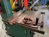
The scrap of L-shaped plywood on the saw table had served us well. but would like something better.

On edit: I was thinking the sprocket side of the Jaw would need to fit into the chain like a normal sprocket and the edges would need to be relieved so the chain isn't draging on the table, but looking at pictures I guess it doesn't matter. They just have a curved profile to fit the outside of the chain, so KISS just make it out of some one solid 1/2" plate. I do like the DoAll handle design of using a couple file handles with some file tang shaped spikes for them to mount on.
 
Last edited:
If you only had a band saw could you make one ?
Try SendCutSend.

-D
If you had one in front of you, you would not ask that question. Please remember that it is designed to not only push, but be pulled by the saw's weight driven cable feed system. Believe me, it is cheap at $410.. On that sytem the two cables couple to an industrial chain that links with teeth on the pusher. If you think that is expensive, price the cost of their fence!. I think the last time I checked it was around $1800. I made the complete cable feed system, because parts were not available. I also made my fence, but I bought the pusher.
 
Last edited:
Given enough time, yes I could cut one out on the same saw, but I think having a shop with a plasma table cut it out would be much more economical. I'd think it would be cheaper than the OEM piece too (minus some assembly labor and a pair of handles), but I might just have to swallow my pride and buy an original.
 
Given enough time, yes I could cut one out on the same saw, but I think having a shop with a plasma table cut it out would be much more economical. I'd think it would be cheaper than the OEM piece too (minus some assembly labor and a pair of handles), but I might just have to swallow my pride and buy an original.
"Assembly" ???
Make your CAD file for the plasma to have the handles integral to the burn part.
Bend them UP after plasma cutting.
It's an expendable piece.
This ain't rocket surgery.... :crazy:
 
"Assembly" ???
Make your CAD file for the plasma to have the handles integral to the burn part.
Bend them UP after plasma cutting.
It's an expendable piece.
This ain't rocket surgery.... :crazy:
Depends how I make it. Cut from one solid plate I'll need to at least make the handle tangs separate and bolt/weld them on. If I make it as a lamination of three plates and weld together, then yes bending the file handle tangs out from the top plate would be an easy way to go. It would likely be cheaper too cut from 3 thinner plates.

Yes the first step is to get to doodling in CAD and then see what it would actually cost to have the piece(s) cut out, and then figure from there. It doesn't have to be JUST like DoAll's, and the manual function of it is fairly simple and open to interpretation, but I want to be sure it mates with the auto-feed chain as it should.
 
One of those things where you will spend more time messing around than just buying the thing.......
Mine has been going for 15+ years, V36 and friction saw...never broken.
I have all the equipment to make one...still wouldn't do it.
But then I'm coming from a business perspective.......I can produce way more income in the time it would take to one-off the thing.
 
Look at laser cutting not plasma. I have a laser shop cut clutch plates to fit closely to a hub that is cut in a gear shaper, it's truly amazing how close they can make it fit first try. I can send them a new DXF with the cut line offset .006 and the parts come back .006 bigger. The chain looks like bicycle chain, I'm sure it's a standard pitch. If you cut 3 layers, you could put short sections of sprocket teeth on the center piece to engage the chain rollers, make that center piece a larger radius than the top and bottom the rest of the way around between those sprocket segments so that it would fit between the side plates of the chain and keep it up off the saw table. You could make the handle stubs integral with one layer as above or improve them, I've never been satisfied with my handles. 2 pool ball size knobs on bolted on extensions might be better. Laser would allow you to cut the steps on the inside of the V same as OEM and it would look nearly OE. I even have them laser cut small screw holes in my parts and I swear they are on location nearly .001, you could laser a few screw holes and bolt the 3 layers together with a couple FHCS, maybe even make it modular and stack them up as desired. I'd bet the 3 pieces could be well under $75. I'll take a set because mine was sawed through and brazed back together long ago, and I'd like to make my own handles.

i also have the ratchet feed mechanism that pushes the jaw from the back, anyone else have that?
 
Last edited:
Ours has the screw feed attachment, the one that looks like a cross-feed screw and nut with a point on the end. It's handy when sawing thicker pieces, and not difficult to use but feels a bit like backing up a trailer steering the cut.
 
  • Like
Reactions: Mud
I really do think 3D printing is a very good option. It could be printed thicker than the metal original. Made from PETG it would be very strong if properly designed.

I'll admit I am speaking from the disavantage of not having used an original. But it seems like this should be pretty easy to draw up and print. My biggest limitation is my build plate dimension. However, making a two-part pusher that would bolt and glue together would get around that problem. My saw is smaller. So, a smaller pusher would still be very useful. And the larger the workpiece, the less of a safety hazard to your fingers as a general rule.

I'd be interested to hear what folks think is the minimal and also the optimal size. Are the other features that would be nice to have?

Denis
 
I’ve posted a few pictures of things I’ve made for my 20” Powermatic bandsaw including a pusher. The pusher is 19” wide and has a 9” depth to the center V. It is 1” thick. The top piece is ¼” plate steel. The bottom is white plastic wood from Lowes. The plate and the plastic wood are contact cemented together. The plastic on the bottom is non-marring and low friction on the bandsaw table. I cut it out on this saw and the holes were made with a hole saw. I made mine before I knew you could buy one, but it was simple enough. By the way I saved the poster board pattern if anyone wants it.

I’ve also posted a picture of my Heinrich bandsaw vice. Between the two, they cover my needs pretty well.

IMG_1018.jpg IMG_1020.jpg IMG_1023.jpg IMG_1024.jpg IMG_1025.jpg
 
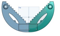
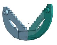
I thought it might be interesting/fun to draw something up that I could print in PETG in two parts and join using steel or aluminum plates for and aft. Rivets or countersunk-on-the-back flat-head screws could be used. Overall dimensions are 14" radius and about 10" height. I drew it 1/2" thick---it would be quite strong and the PETG is naturally fairly slick. If some moron (me) sawed it in half, it would take only a few hours print time to make a new one.

In my CAD program it would be easy to scale this up of down. I did make bosses for handles with countersinks for 5/16 bolts. And, yes I could not help myself when it came to the "eyes." Not sure if I would leave them in the print or not. ;-)

Pusher Bandsaw.jpg
Pusher.jpg

Back of Pusher.jpg

A couple of printed handles would complete it.Handled Pusher.jpg


Denis
 

Attachments

  • Back of Pusher.jpg
    Back of Pusher.jpg
    260.2 KB · Views: 5
Last edited:


Back
Top