What's new
What's new

Does GD&T perpendicularity tolerance zone travel with positional tolerance

sendithard

Plastic
Joined
May 18, 2021
In the below sketch I'm showing a large .500" GD&T positional tolerance zone for clarity. In reality, I understand this would be something like .01". The .250" circles would be drilled hole locations. If one drills a hole at the extreme allowable distance from true position does one get the same perpendicularity tolerance zone as you would if you drilled anywhere else? So basically, I'm asking if this tolerance zone 'wrapper'(.04" in the picture) travels with your hole location? I'm curious if the perp tolerance would just be large like around .05" and tied down to the true position location and just stays there.
perp.JPG
 
In the below sketch I'm showing a large .500" GD&T positional tolerance zone for clarity. In reality, I understand this would be something like .01". The .250" circles would be drilled hole locations. If one drills a hole at the extreme allowable distance from true position does one get the same perpendicularity tolerance zone as you would if you drilled anywhere else? So basically, I'm asking if this tolerance zone 'wrapper'(.04" in the picture) travels with your hole location? I'm curious if the perp tolerance would just be large like around .05" and tied down to the true position location and just stays there.
View attachment 326871

You need to show the actual FCF with datum callouts to work out what the true tolerance zone would be.

Having said that, the centerline of your feature needs to be fully within the tolerance zone for position. So the part of your perpendicularity zone that is drawn outside of the position zone is invalid. That fails the position requirement.
 
Thanks for the reply. This is a simple case. Imagine a square block. I callout a .250" diam hole +.005/-.000 So at .250" hole we have MMC and a positional tol of .500" in this example(massive I know) from AB both walls of the square. So in the picture both .250 holes drilled are drilled within positional tolerance. My question is if the perpedicularity tolerance zone from surface C travels to wherever the drilled location is or is it tied to the hip with true position.

edit: below is a pic whereby you can see the zone I am asking if is tied to true position or if this zone travels around with where ever you drill the hole. tol.JPG
 
How about you just post the picture with the FCF. The picture is probably clear in your mind, but you aren't doing much of a job describing it. GD&T has standard symbols for a reason. If "imaging" them from text was the way to go, we wouldn't have the symbols.
 
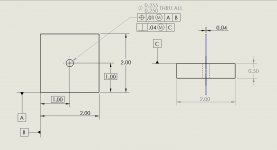
Below is the drawing. For example, in the right drawing there is a centerline for the hole. If you drilled perfectly in true position and called out a Perpendicularity tolerance of .04 to Datum C then there would be a diameter wall wrapped around that perfect axis that cannot be breached by your drilled axis. BUT, let's say you miss drill by the max or .005 from perfect. Does that blue wall outline I drew in the right drawing travel .005 away from true center basically following your mistake in drilling incorrectly, or is the .04 tol zone tied to true position?

Thanks.
perpy.JPG
 
As mentioned above, the .04 perpendicular tolerance zone is pretty much voided by the tighter positional tolerance zone of .01. Any perpendicular tolerance cannot be larger than the positional tolerance zone. In this manner, you can control control perpendicularity and position.- the axis of the hole MUST lie completely within the tolerance zone, regardless if it is simply translated or tipped or both. Just FYI your datums for your FCF for your positional callout should be C-A-B if i'm not mistaken.
 
The perpendicularity is an additional requirement that travels with the hole actual position. First, all portions of the hole must be within the tolerance zone. Then, assess the perpendicularity of the hole without regard to its position.
 
As mentioned above, the .04 perpendicular tolerance zone is pretty much voided by the tighter positional tolerance zone of .01. Any perpendicular tolerance cannot be larger than the positional tolerance zone. In this manner, you can control control perpendicularity and position.- the axis of the hole MUST lie completely within the tolerance zone, regardless if it is simply translated or tipped or both. Just FYI your datums for your FCF for your positional callout should be C-A-B if i'm not mistaken.

Dan,

Thanks for the input. I believe you are correct that the primary datum should show surface C.

The perpendicularity is an additional requirement that travels with the hole actual position. First, all portions of the hole must be within the tolerance zone. Then, assess the perpendicularity of the hole without regard to its position.

Gbent,

Thanks, I was under the assumption the tol zone could travel to any location that was drilled within tolerance, but somehow started to wonder if it was tied to the true position. Much appreciated to all.


Back
Top