Lester Bowman
Hot Rolled
- Joined
- Apr 9, 2011
- Location
- Modesto california USA
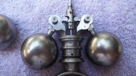
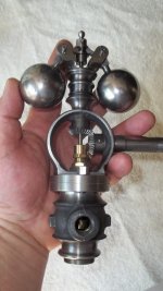
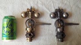
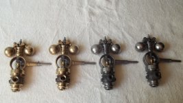
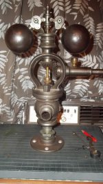
A bit of progress... showing how the top pieces fit together in harmony. Two done, five more to go. Then time to move on to the valves.
Follow along with the video below to see how to install our site as a web app on your home screen.
Note: This feature may not be available in some browsers.
") I am glad to be nearly finished !
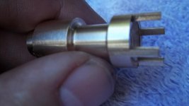
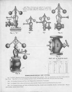
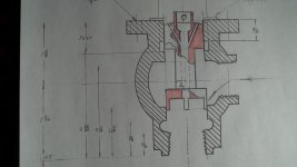
I am glad to be nearly finished !I understand clearly now. Perfect explanation and the drawing helps - thank you!. I may tackle making a governor some day, a first generation Judson... but only one... not multiples for my larger box bed steam engine. JakeBest I can do Jake. Here is a poor pic of a sectioned Judson valve. The Valve prongs simply engage with the bottom seat to keep axial valve alignment. The " cutout" portions form the actual valve opening.
The idea behind it is this. Steam enters pressurizing the bottom chamber. It then enters the central hole through the center of the valve via the bottom pressurized chamber. It then pressurizes the top chamber with approximately the same steam pressure as the bottom chamber. This results in equilibrium of pressures on both end of the valve.
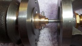
This was an early form of balancing the valve within the governor body stabilizing valve function.
This is the earliest generation Judson, combined-valve governor. Jake
Les.Notice
This website or its third-party tools process personal data (e.g. browsing data or IP addresses) and use cookies or other identifiers, which are necessary for its functioning and required to achieve the purposes illustrated in the cookie policy. To learn more, please refer to the cookie policy. In case of sale of your personal information, you may opt out by sending us an email via our Contact Us page. To find out more about the categories of personal information collected and the purposes for which such information will be used, please refer to our privacy policy. You accept the use of cookies or other identifiers by closing or dismissing this notice, by scrolling this page, by clicking a link or button or by continuing to browse otherwise.