What's new
What's new

Electrical Questions - RPC Controls

Yes, I'm not sure what to think at this point myself.

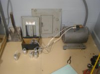
There are only 3 leads in the peckerhead, labeled 1, 2 and 3. There are 2 leads into the box on top, labeled 2 and 3. I think the wires out of top have continuity with corresponding numbered wires in the peckerhead, will verify tomorrow.

I attempted to send an as-is schematic to mfr today for verification, their inquiry system kept rejecting it, I will call again tomorrow and see if they can provide a direct email address.

Current thoughts, yank a few caps and see what happens, if acceptable, run with it for now, only 2 machines really need the 20hp capacity, see what happens when I get to them.

Option 2, yank all the caps, terminate those leads, treat is an an idler and build a control box where legs can individually be balanced.
 
RPC output voltages have been confirmed as being correct by mfr.

Capacitor wiring has been confirmed as correct by mfr, note capacitor wiring schematic below is different than what I posted previously, but what was in the box was properly connected. Cap wiring has been re-done as one of the wires had clearly been running hot.

In new schematic the caps have been numbered, this was for testing reference. With caps 9 & 10 removed no load voltage at panel was 1-3=240v, 2-3=269v, start time increased by a second or 2. With only cap #1 removed, no load voltage at panel was 1-3=246v, 2-3=275v, little more hum noise. With caps 1 & 4 removed, no load voltage at panel was 1-3=240v, 2-3=270v, start time increase and a hum.

With a 1.5kw (approx 1.3hp) motor running, with caps 9 & 10 removed, voltages were 1-3=235v, 2-3=260v. Thermal relay on machine still tripped after about 3 minutes run time, re-wired so the artificial leg goes thru center terminal, and it still tripped.

I'm not qualified to make the decision to remove more caps, if you are, tell me which ones, and explain why.
 

Attachments

  • rpc testing.jpg
    rpc testing.jpg
    87.1 KB · Views: 23
  • rpc hot wire.jpg
    rpc hot wire.jpg
    88 KB · Views: 16
  • rpc cap wiring.jpg
    rpc cap wiring.jpg
    91 KB · Views: 18
  • testing results.jpg
    testing results.jpg
    92.8 KB · Views: 17
After staring at the mfr schematics for wiring in the magic fix transformer, I am completely lost. I know how to wire a transformer for 220 to 440, and I know how to use a multi tap transformer to get the power I need, 3 wires in, 3 wires out, that is easy. So without some assistance on how to use a buck/boost transformer as mfr indicates, I am lost, and if I don't understand it, I can't wire it.

Looking at the mfr's product literature for the magic fix, the direct cause of my problem is running too large of an rpc on too small of a load, properly loaded the voltages should drop lower than what I am currently getting. I will wire in next machine with a 3hp motor and see what happens to voltage, maybe the quick/easy/cheap fix is to add a 5hp idler.
 
Even cheaper solution should be to disconnect some capacitors.

Start with zero capacitors. See what you get. At no load, and with a load.

Add some capacitors back if needed. Don't go over a total which raises the no-load voltage to 10% over the nominal line volts, phase-to-phase. If possible stay around 5% to 7% boost, no load.

I don;t care what they say, the 276 volts (or whatever) is too high

If you can't find a workable solution that way, then you can consider a transformer, which will work fine. For now, don't worry about it.
 
Looking things over I have figured out why the thermal switch on first lathe is tripping, it is only rated for 6A which was fine for the 440v connection, but at 220v the motor is drawing 8.6A. The things that will make you chase your tail....
 
All capacitors removed, no start.

Replaced motor control switch with a 10A switch, got about 20 minutes run time before it tripped. Just motor running, no work being done.

Could I get some assistance on sizing/selecting the right buck/boost transformer and how to wire it?
 
First, what were the voltages when it was running? If you have large voltages, things probably will not go as they should. The motor wants to see well balanced voltages.

The idler needs the START caps. Let them alone, without them it wont start. They are the ones that are (usually) removed from the circuit when the idler has started. Usually (not always) they are black plastic cased typical electrolytic type motor starting capacitors.

The run capacitors will be motor-run types, usually in a metal case.

A couple good clear pictures here would be good, showing the capacitors, and their wiring clearly.

The load motors should run with no RUN capacitors installed. But, the motor may not be getting balanced voltage. The generated leg will normally be low with no capacitors or other devices to raise voltage.

So the cheap way here, is to add them back one by one, UNTIL.............

1) the run voltages are balanced

or

2) the no-load voltage exceeds 10% higher than the input voltage (measured line-to-line).

Whichever occurs with fewer capacitors.


If there is no satisfaction at that point, THEN more expensive solutions like a boost transformer can be discussed.
 
JST

The unit is a phase-a-matic. Rotary Converter On Phase-A-Matic, Inc.

Pictures are in post 42. The capacitors are all metal cased. The original ones were replaced about 10 years ago with identical ones.

Phase-a-matic says they use specially wound Baldor motors- and their design uses NO start capacitors, relays or contactors.
They talk about their rotor being a special design, not a modified electric motor rotor.

That it did not start with no capacitors makes me think the "run" are also functioning as "start" capacitors.

dalmatiangirl61

You keep giving us only part of the information we need. We need numbers.
OK- my statement does not apply to the last post- if it does not start- you have no running voltages to measure...

Do not give up on the capacitors yet.

You have 10 capacitors. In an earlier post you indicated removing one capacitor reduced the L2-L3 voltage to 275, and removing two reduced it to 269/270, and when 1.5 kw motor run, it reduced to 260 volts.

From the above we know you need more than 0 capacitors, and less than 8.

Try starting it with 4 capacitors. If it starts, measure the voltages. Remove one capacitor at a time until you you have L2-L3 voltages in the 260 volt range with no motors running. Then add your 1.5 kw moptor - or better yet the 3 hp machines mentioned. Measure all voltages ( L1-L2,L1-L3,and L2-L3) every time and let us know what you find.

If it does not start with 4 capacitors add one capacitor at a time until it does- then start measuring voltages as above.
 
... Can caps go bad by increasing capacitance? ...

No. Often newer DVMs like those by fluke have capacitor value test features. Handy. If you have an old-school simpson meter you can:

1) disconnect and remove the capacitor.

2) short it.

3) set the meter to RX10 or RX100 acale.

4) watch the needle when you make the connection to the capacitor - it should briefly read towards short, and then slowly decay to infinite ohms.

5) again, do not have the capacitor under test connected in any way inside the converter.

Motor capacitors like this typically fail bg going short-ish, which means they get hot, which means the liquid dielectric boils which means the internal can pressure spikes, which means the top bulges up, which disconnects the two top terminals from the internal workings, which clears the short in the circuit and prevents the unit from bursting. It's a safety feature. If the tops are bulged, definite failed unit. If not bulged, then maybe yes, maybe no, failed.
 
Looks like I missed that post.

Yes, the start can also be the run capacitors. My smaller Arco is like that. One capacitor that does both.

The issue is when the start capacitors are already too much for the "run" condition.

The Arco solves that by the design.... it is a "double cage" rotor, where an outer higher resistance cage gives easy starting, so that the start capacitor can be small and still function OK as a run capacitor.

Once it is spinning, the slip frequency drops and a larger, higher inductance lower resistance cage takes over, providing good performance as an idler.

Presumably that is what they do. But if the voltages are that high, it may be required to remove some start caps after starting..... It will definitely be needed in the case of switching to a boost transformer approach.

It is "possible" to use a buck transformer to lower the high voltage. But I see that as putting a "patch over a patch", as opposed to fixing the problem that exists, since the capacitors raise the voltage, AND are an inferior way of doing it to begin with..

It is possible that fewer capacitors will still start the idler fine, and avoid the extra high voltage issue. That would be the thing to try first.

Remove capacitors until voltages are acceptable, or until the motor begins to have trouble starting, whichever comes first. Then evaluate the results.
 
For the lathe run test yesterday all caps were back in place, I wanted to know if the old switch being under rated at 6amps was the problem, the new switch rated at 10amps should handle the load. Considering that it ran for 20 minutes before tripping, leads me to thinking the voltage imbalance is the problem. At this point I think leaving the rpc as mfr made it is the best course of action.

I read multiple threads yesterday of other people with store bought rpc's having similar problems with voltage imbalance and high voltage on the artificial leg, in each case the suggestion was using a buck/boost transformer, but I did not see any discussion on how to size it, or a wiring schematic. Most threads ended with no resolution, a few ended with "I found a transformer (no pic or part# or schematic given), played with wiring and got it right". Which just leaves me hanging.

Using a transformer may be a patch, but it looks like that is what I need to do, so where do I start?
 
Well, mcmaster carr does sell buck/boost xfrmers...

I'm looking at the McMaster Carr page, description is clear. Where its all falling apart is input is listed as 120/240v, and output is 12v/24v, I am clearly missing a crucial piece of information or understanding. And I'm not sure if I need a single phase unit to adjust the 1 leg, or the 3ph unit to balance all 3.
 
If you have the neutral available, one will do it fine.

But, did you try it as far as starting with fewer capacitors? Because, as mentioned, fewer should reduce the voltage. It may take just a couple fewer, and I'd not expect that to foul up the starting very much if at all.

3 choices.....

1) Reduce capacitance by removing capacitors one at a time until it is OK (OK means it starts, and no load/light load volts are not excessive, but it still holds up voltage with the loads you have. Likely to work, might not work if you have to remove too many, very easy to try. Cheapest solution by a good margin if it does work.

2) Leave all the capacitors, add a step-down transformer to give you lower voltage on output. This definitely reduces voltage, works best if you have a neutral available, voltage is less stable due to using the capacitors.

3) Use the capacitors just for starting, take them out for running (just as if they were electrolytic), and use a boost transformer to give you the higher voltage. Should give a more stable voltage, requires the transformer, access to neutral, plus a contactor and voltage relay etc to remove the capacitors.

The transformer should be sized for the output current you need, plus a margin of maybe 25% to 50%. You likely do not need more than twice the load current capability. The margin is there to reduce the overall impedance of the system. Too big just draws extra current, so huge is not better. For maximum ability to adjust, have the current rating with the largest boost voltage.
 
I spent a little time on youtube U, I now see how to use a buck boost transformer to take single phase 208v to 240v, or 240v to 220v. Looking at the info on M-C it looks like a broader range of voltage transformation is possible depending on how the taps are wired, still working on understanding that.

On the M-C site they say for sizing the equation is volts times amps, so 240 x 54 = 12960 so I would need a 750 or 1000va single phase transformer? Is that correct?

Still a little fuzzy on how to apply this to the output of a phase converter.

Edit: I have a 500VA 120/240v primary, 24vac secondary general purpose transformer, can I wire this per the different configurations shown on the M-C site to see how it affects outputs? I need to play with this to wrap my head around it.

Edit again: Seems the 500va transformer won't work for fiddling, the primary coil is just one coil tapped at different locations for 208/230/460v, not reconnectable as 2 separate coils as indicated in the M-C diagrams.
 
Last edited:
If you have the neutral available, one will do it fine.

But, did you try it as far as starting with fewer capacitors? Because, as mentioned, fewer should reduce the voltage. It may take just a couple fewer, and I'd not expect that to foul up the starting very much if at all.

3 choices.....

1) Reduce capacitance by removing capacitors one at a time until it is OK (OK means it starts, and no load/light load volts are not excessive, but it still holds up voltage with the loads you have. Likely to work, might not work if you have to remove too many, very easy to try. Cheapest solution by a good margin if it does work.

2) Leave all the capacitors, add a step-down transformer to give you lower voltage on output. This definitely reduces voltage, works best if you have a neutral available, voltage is less stable due to using the capacitors.

3) Use the capacitors just for starting, take them out for running (just as if they were electrolytic), and use a boost transformer to give you the higher voltage. Should give a more stable voltage, requires the transformer, access to neutral, plus a contactor and voltage relay etc to remove the capacitors.

The transformer should be sized for the output current you need, plus a margin of maybe 25% to 50%. You likely do not need more than twice the load current capability. The margin is there to reduce the overall impedance of the system. Too big just draws extra current, so huge is not better. For maximum ability to adjust, have the current rating with the largest boost voltage.

I have a neutral/ground in the panel, it is combined, not separate.

At this point I am hesitant to remove any more caps. I have confirmed with the mfr that the cap bank is correct as they designed it, and the output voltages are "correct". I think the best course of action now is to correct the voltage. The mfr wants more than I am willing to throw at this unit for their transformer fix. I took a hard look at the competitions rpc, it has a circuit board in it, which gives me pause. I just made an offer on a 1000va buck boost transformer, cheap enough that I'm not out much if it does not fix the problem, and I get an education to boot:D.
 
"As they designed it". My question is "what does correct mean?".

There is no way 276VAC is correct for any 240V nominal system, not in my book, anyhow. That's what you get line to neutral from a 480V system! (and things such as lights are made specially to handle that)

They seem to have a strange version of "correct".

Aside from the issue of starting the RPC idler, there is clearly too much capacitance in the system. That's how the voltage gets high.

And, the higher the boost, the less stable the boosted voltage is. So it is self-defeating in a way.

You can cut up the corpse with PAM later.... To get this thing off the dime at minimum cost, your best move is to find out what capacitance will keep the voltage at least under 264V.

And, how little the idler will start with.

Hopefully, the idler will start reliably with less capacitance than that which holds the voltage to a reasonable level. If so, then it will be even more reliable starting with the max capacitance you can put in without exceeding the 264VAC.

They should be good with that. This nonsense of 276VAC being "normal" is just that, IMO. It is over what any 240V device is intended to withstand.
 
Nobody's floated the idea of using a potential relay to connect dedicated start capacitors, which are then switched out of the circuit once it's up to speed?

Then the run capacitors can be tuned for correct manufactured voltage. This is the way the home-build folks do it. Unless the converter in question is built on a 2X4 base....
 
That was option 3 above....... except I suggested just doing the boost transformer at that point, in place of capacitors.

It's viable, but not the easiest/cheapest solution.
 
"As they designed it". My question is "what does correct mean?".

There is no way 276VAC is correct for any 240V nominal system, not in my book, anyhow. That's what you get line to neutral from a 480V system! (and things such as lights are made specially to handle that)

They seem to have a strange version of "correct".

Aside from the issue of starting the RPC idler, there is clearly too much capacitance in the system. That's how the voltage gets high.

And, the higher the boost, the less stable the boosted voltage is. So it is self-defeating in a way.

You can cut up the corpse with PAM later.... To get this thing off the dime at minimum cost, your best move is to find out what capacitance will keep the voltage at least under 264V.

And, how little the idler will start with.

Hopefully, the idler will start reliably with less capacitance than that which holds the voltage to a reasonable level. If so, then it will be even more reliable starting with the max capacitance you can put in without exceeding the 264VAC.

They should be good with that. This nonsense of 276VAC being "normal" is just that, IMO. It is over what any 240V device is intended to withstand.

I am in full agreement that the voltage is not correct, and have been fighting that issue since the day I got this. According to mfr the no load voltage between legs 2-3 should be 280v, and with a proper load it should drop down to 240v, short of the back burner air compressor nothing I have today is going to properly load it. I have been into every part of this thing, if there is something special about it is in the windings, and I'm not qualified to fiddle with those.

I am surprised there is not more documentation of people having these issues, maybe they don't check voltages, maybe they just buy the fix-it transformer, IDK. But looking at some old threads here it is not a completely unknown issue.
Phase converter voltage issues I THINK causing problems with new lathe. Please read!

How Does One Test an RPC?

Question About Phase Converter Voltages


Back
Top