What's new
What's new

Electrical Questions - RPC Controls

dalmatiangirl61

Diamond
Joined
Jan 31, 2011
Location
BFE Nevada/San Marcos Tx
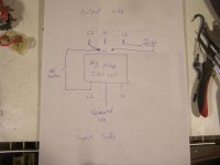
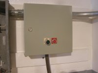
I'm down to the finishing touches for getting my rpc connected and have a few questions, second pic is how I think start/stop switches should be wired, just need confirmation that is correct, or told how to change it. 3rd pic is the switches, are these suitable to wire in as drawn in pic 2, or should I use these to control a smaller contactor or relays?? No amp rating on the switches, and not sure amperage draw on coil, I think these switches will be fine, need confirmation.

I have an ICM450 voltage monitor to install, the manual assumes you have 3ph and indicates wiring going to both sides of contactor, manual also shows load side connections as optional. It would seem to me that if I wired line and load side of ICM, when contactor is open (rpc off), it would show a fault as it is only getting L1 & L2. So I'm thinking it would be best to just wire line side to output side of mag contactor, and skip load side connections. Any thoughts?

I've been getting by for past few years running an extension cord from rpc to machines, just 1 cord, its a pia. The goal of getting rpc wired into a breaker box is so that at some point everything is in conduit, but that is still a year, maybe more, away. So a thought that occurred to me is to put a female plug on the back of each machine so they can be daisy chained together. Run extension cord to first lathe, plug second lathe into first, 3rd into second, etc. This is a 1 person shop, rarely have 2 machines running, rpc can handle up to 60 combined hp. I'm sure its not code, but I think it would work fine. Thoughts?
 

Attachments

  • rpc 1.jpg
    rpc 1.jpg
    91.1 KB · Views: 95
  • rpc 2.jpg
    rpc 2.jpg
    89.4 KB · Views: 93
  • rpc 3.jpg
    rpc 3.jpg
    82.6 KB · Views: 89
The only part I can offer is the switches should be fine. They may have the max voltage and amp rating cast into the operator body. You are going to run a neutral for the pilot light. Remember you need the momentary to latch either on a leg at line voltage if 220 is it or an aux contact block.

Do you have the rpc caped for a particular load? If you intent to put plugs on the machines use the standard convention male plug, that way a standard extension cord will work.

Steve
 
The switches wired as shown in the second post should work. I have the same switches in my RPC. I do not recall their rating. I may be able to look that up tomorrow.

I got an ICM450 to see if it would work with my existing home built capacitor start RPC. I have experimented with wiring it in so it receives power from L1 and L2 when the start button is pushed. There is a time delay of some 9 seconds between when it powers on and when it closes its relay- at least with the one I have. This means that the if it is wired to be powered by L1 and L2 after the contactor powering the idler, the RPC will have started and be generating on L3 before it starts monitoring for a phase loss. How to proceed depends on what you want the ICM450 to do. One option is to have the ICM450 relay control a contactor between the RPC and the breaker box. Wired in this way the breaker box does not recieve power until about 9 seconds after the RPC is started. If there is a phase loss the ICM450 shuts off the power to the breaker box, but not the rpc itself, which continues running. You could wire the ICM450 to shut off the RPC, but then you need a way to bypass the relay on the ICM450 for the 9 seconds it would be open, so you can start the RPC.
 
The only part I can offer is the switches should be fine. They may have the max voltage and amp rating cast into the operator body. You are going to run a neutral for the pilot light. Remember you need the momentary to latch either on a leg at line voltage if 220 is it or an aux contact block.

Do you have the rpc caped for a particular load? If you intent to put plugs on the machines use the standard convention male plug, that way a standard extension cord will work.

Steve

There is an aux contact block on the mag, I'm not quite understanding last sentence in first paragraph.

RPC is not capped for load, its been setup for maximum capacity, not because I intend to run multiple machines, but for the hardest/slowest starting applications, the cylindrical grinder and air compressor. Most of the machines are close enough that cord from one reaches the next, using twist lock plugs. Thinking about the layout, I may run 1 cord to power the 3 lathes, another to power 2 mills, the 3 grinders will be in painted area and not far from rpc, so I will get conduit to them.

Edit: Cylindrical grinder would not start with my previous janky rpc setup, pretty sure it was a combination of getting grinding wheel up to speed, undersize wiring, and the fact it was on a 70amp breaker.
 

Attachments

  • rpc 5.jpg
    rpc 5.jpg
    87.5 KB · Views: 48
The momentary start switch needs a way to keep the coil energized after you stop pushing the button. That is generally done with a latch or a wire from a leg on the load side of the contactor IF the coil is line voltage. If the coil is at a lower value control voltage an aux contactor or unused pole on the contactor is used to maintain the current for the coil. When you push the stop button it breaks the other side of the coil field

Steve

Coil is line voltage (220v), so just a jumper from output side of L2 to coil terminal, as drawn in post 2? Crayon colors might help my schematic skills:D
 
I have not found any information on the actual rating of the switches.

I did find some information on the coil characteristics for Allen-Bradley NEMA contacters. Physics being what it is, other brands should be similar.

All the NEMA sizes have coil operating limits of 85 to 110%.
The following is for 60HZ coils. and is in Volt Amps

NEMA inrush sealed
00 70 8
0 192 29
1 & 1P 192 29
2 (2 and 3 pole) 240 29
2 (4 and 5 pole) 315 38
3 (2 and 3 pole) 600 45
3 (4 and 5 pole) 840 58
4 (2 and 3 pole) 1225 60
4 (4 and 5 pole) 1490 96

According to that info a #3-3 pole coil draws 600 volts at 45 amps??? Or am I misinterpreting that? Seems awfully high.

Edit: Any chance you could provide a link to where you found that info?
 
The figures are given for VA, not amps.

First figure is pull-in inrush VA, second is after it closes (sealed).

When an AC coil contactor is open, there is no "core" in the coil, so the impedance is low, lots of inrush current, high VA. After it closes, the magnetic circuit is more complete, inductance goes up, and the AC current goes down to that for the "sealed" VA figure.

Point of the numbers is that you need to be able to supply all the closed contactors, plus the figure for any others that need to close after them. That's why "control" transformers are usually fairly beefy. They need to close another contactor, without letting any drop out that are already closed.

Correct me if I'm wrong, for AC current volt amps is equivalent to watts, so 45 watts at 120V equals approx .4 amps, so the 14 gauge wire I just installed for the switches is adequately sized?
 
JST is correct. My spacing and rows distorted when posted.

The #3 3 pole coil:
inrush is 600 volt amps. For a 120 volt coil: 600VA divided by 120 volts = 5 amps inrush.
"sealed" 45 volt amps. For a 120 volt coil: 45VA divided by 120 volts = .375 amps


This link is not the same document I had printed out, but it has the same information. https://literature.rockwellautomation.com/idc/groups/literature/documents/td/500-td014_-en-p.pdf

You might think about a 3 phase panel and then wire in conduit on the ceiling to near the machines, then cable dropping to the machines. For me- and doing it myself, wire in conduit cost less than cable. That left me with cable needed for drops, which I terminated in twistlocks over head high. It would cost less to have just wired in the cable and skipped the plugs and connectors.

The installed panel is 3ph, just waiting on some breakers. I'm still working on old paint removal in the rest of the shop and will not be installing electrical in that area until finished with repainting. I got the pictured area mostly finished this past summer because I need to move forward with this install, and needed to see some progress to save my sanity.
 
As JR Thiele replied, yes.

It was for a long time, and may still be, that wires in any controller etc covered by UL508 had to be no smaller than 14 ga. That would certainly carry either the inrush or the sealed current from several contactors, which may be one reason for the rule.
 
I finished this installation today, and it seems to be running fine.

Last time I checked the voltages on legs was 2014 according to my notes, so I checked them again today.
L1 - N 117v
L2 - N 117v
L3 - N 243V These numbers align with previous readings, unfortunately I did not record the L-L readings at that time.

Todays L-L readings

L1 - L2 237v
L1 - L3 253v
L2 - L3 282v

According to my previous notes PAM tech said L1 -L3 and L2-L3 should read 270v. I'm not quite understanding how if L1 & L2 have the same volt reading, when crossed to L3 I'm getting different voltage readings? I will most likely call PAM tech tomorrow. But if anyone has thoughts I'd like to hear them.
 

Attachments

  • rpc 7.jpg
    rpc 7.jpg
    88.1 KB · Views: 20
  • rpc 8.jpg
    rpc 8.jpg
    100 KB · Views: 17
Do not know about PAM tech advise. Usually you want L1-l3 and L2-L3 to be 8 to 10 % above L1 -L2. For 240 volt L1-L2 that is 264 volts. That increase in volts is produced by the run caps. You want the voltage to be high at idle, as it will drop under load. I assume the results posted are with the idler only. From what you have posted it looks like you need less capacitance between L2-L3 and a little more between L1-L3.

What do you get when running a machine?

Yes, those are no load readings. Hoping breakers arrive tomorrow, and need to wire in an outlet, before I can get run readings. I replaced all the caps in 2012, wondering if one has gone bad.

Edit: I seem to recall L1-L3 and L2-L3 being same before, but since I did not write it down, cannot confirm.
 
Just got off phone with PAM tech support, they advised checking the capacitors. If I see any bulging that is easy enough to diagnose, if they look fine I may just replace them all. Tech thought L3-N @ 243v was too high, and L2-L3 @ 282v was too high.
 
I opened up the box of caps a few weeks ago, nothing appears to be obviously wrong, so I've been "thinking" about it while getting other electrical work done. Here is my thought process, feel free to correct it: If voltage is too high it means there is too much capacitance, but when caps go bad they lose capacitance (I think?), so caps going bad is probably not the problem? Can caps go bad by increasing capacitance? Would resistance in the cap wiring affect capacitance? Original caps were soldered, when I replaced them in 2012 I used crimp on spade connectors, if a crimp was bad there would be no continuity, which would mean voltage would be low, but if just a poor connection maybe resistance has an effect on voltage??? There are only 2 wires coming out of idler into cap box, labeled 2 and 3, I can only ASSUME these are the same 2 and 3 in the peckerhead, with 3 being the generated leg. Mfr used a crimp connector (hollow metal tube crushed as needed) to connect #2 and #3 wires to the 3 wires feeding cap bank, this seems to me to be another location for a poor connection with resistance, and makes servicing cap bank a pia, I'm going to replace those today with a serviceable/better connector.

The caps in it now are CSC brand, made in Mexico, I'd like to test them, but a decent tester would cost as much as 10 new Gentec made in Mexico caps, so........... I did look at Amrad made in USA caps, but at $30 each its not quite cheap.

A penny for your thoughts!


Back
Top