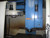
13engines, thank you for all your help. You are correct in this has a lot of hours & abuse, has many areas in the "T" slot area that were cut through the part in to the table. The plan is to cut & drill a tooling/fixture plate of steel to accept vises and a "grid type" hole pattern that agrees with the shapes to be cut. Most parts will be to look at, so only surface finish needs to be good. I plan to adapt a High Speed 220v single phase spindle in to the BT-40 because .031 diameter tool will be used to get detail.
Are there any workarounds for chip guards, all the parts are there but a lot of hours running, wonder how well they will telescope, they move just, but rubber part of the scraper seal is long gone, the underneath needs work.
You asked about the parameters, the attached files are what I have to start with, the small amount I recall from the discussion with prior owner was the 1 file needs to be edited, some, not a lot. I will know more soon. I have all 5 factory manuals. Attached are O M Options, the other file would not attach so copy and paste, is below.
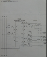
I understand your suggestion about the 2 legs of the 3 phase. My real hope is I can disconnect the spindle and run on single phase, please see the pic of "control voltage" diagram. It looks like this is single phase, or is this just control voltage, and that the power or volts it controls are the 3 phase in question. I welcome your thoughts. If necessary, fake/change settings, so no error codes are activated.
This is one of the files opened in a text editor:
O9020(CALL 20T USED)
IF[#1000EQ1]GOTO102
M31T#20(CHECK TOOL N0)
G04X0.05
#145=0
#146=0
#147=0
IF[#1000EQ1]GOTO299(T CODE IS SP. TOOL NO)
IF[#4006EQ21]GOTO101
IF[#20EQ0]GOTO100(T ALARM CHECK)
IF[#20GE21]GOTO100(T ALARM CHECK)
IF[#20EQ#0]GOTO100(T ALARM CHECK)
#149=#4003
#148=#4001
G0G91G80G49M19
M66(TOOL CHANGE IN PLC)
IF[#1004EQ1]GOTO30(SP TOOL=0)
M17(BACKUP D440TO D481)
WHILE[#1002EQ0]DO1(Z1 ZERO RETURN)
#146=#146+1.
IF[#146GE4.]GOTO99
G30Z0
END1
N30
IF[#1004EQ0]GOTO20(SP TOOL=0)
WHILE[#1003EQ0]DO1(2Z ATC POS)
#147=#147+1.
IF[#147GE4.]GOTO98
G28Z0.
END1
N20
M41(MAG. FORWARD)
M32(SPINDLE TOOL UNCLAMP)
WHILE[#1003EQ0]DO1(Z2 ZERO RETURN)
#147=#147+1.
IF[#147GE4.]GOTO98
G28Z0
END1
T#20(MAG. ROTATE)
WHILE[#1002EQ0]DO1(Z1 ZERO RETURN)
#145=#145+1.
IF[#145GE4.]GOTO99
G30Z0
END1
M33(SPINDLE TOOL CLAMP)
G#148G#149
M42(MAG.BACK)
GOTO299
N98#3000=1(ATC POS2 LS ERROR)
N99#3000=2(ATC POS1 LS ERROR)
N100#3000=3(T/M6 ERROR)
N101#3000=4(UNIT MODE ERROR)
N102#3000=5(PRESS RESET KEY)
N299M34
G20
N300M99
%
Yes, keeping fingers crossed.
All suggestions warmly welcomed, many thanks.