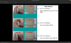
What's new
What's new

Fanuc Alpha Series control, need help with a few cable connections

Just some potentially helpful tid-bits. (Pun intended)

There is a Parameter that turns on a display of corresponding letters in front of Parameters and Diagnostics. Like XYGF and so on. I couldn't find it but I know it exists. You might dig for it. It's helpful in steering you to the correct Addresses as they're preceded by the appropriate letter. All of this stuff is in the Fanuc Manuals.

The Signal addresses below might help you test your limit switches in E-Stop:

Overtravel Signals: +XYZ X20.0 - X20.3 //// -XYZ X20.4 - X20.6
Deceleration Signals For Reference Position Return: XYZ4 X16.5 / X17.5 / X18.5 / X19.5
Detection of One Turn of Pulse Coder: DIAG 27
Status of Signals Supplied from the machine to the PMC: DIAG 16 thru 22
 

13engines, thanks! I am not confident nor do I know my controller and don't want to goof up. I have read parts of several of the manuals, the blinking "not ready" message is still present at the bottom of the screen. Currently, I am reading the operations manual, but not knowing enough to understand what the next logical step is, makes for slow but safe progress. I was not expecting to need to become knowledgeable about "parameters" so early in the ownership of this mill.​

I have had excellent support from the machine builder YCM, I asked about the way covers and the attached info was suggested. I have not measured to see what profile fits the best in my cover, but looks very promising. After I get the control figured out, I will work on the way covers.​

Many thanks for the great help, I know I am getting close.
 

Attachments

  • WayWiperSuperMaxResized.png
    WayWiperSuperMaxResized.png
    480.9 KB · Views: 8
Those Way Cover seals look like mine. If you look around you might find a Hennig name plate on one of your covers. I think I bought my replacements straight from Hennig, but that was 15-20 years ago. Regardless... you're on the right track. It's a little tricksy getting the way cover sections apart. Requires a touch of spreading and the proper angles. You'll figure it out.

Vancbiker might be better able to help you get past that Not Ready alarm. Some things are beyond me, especially without being there looking the problem in the face. If you can get the machine up and in E-Stop, you should be able to verify all the switches like I mentioned earlier. If they all check out, give the Zero Return a try. You can't start machining until you get the Zero Returns satisfied.

There are some really good YouTube vids about Fanuc by John Robbins of TIE. Like how the machine talks to everything. Here's a great one to start. There are others. I wish I knew a 10th of what this guy knows. Hopefully it's not TMI for were you're at.

 
This is something a Fanuc person has shared. How to read the diagnostic codes:

"Diagnostic X0021.4 is X0021 00000000 bit 4 is the underlined one.

The bits are counted 76543210."

This is what a technician has shown to me and has value. Many thanks!
 
Shoot... sorry, for some reason I thought you already had that figured out. Yes just like that. It is not just Diagnostics but also regular Parameters too.

You've already noticed that many or most Parameters are 8 bit sequences. 00000000

Many time they're just a plain number like 32. A lot of them are also entered in Least Input Increment, which are usually done in Metric. Like 500mm would be entered as 500000. 1/2 a mm would be 500 Note leading zeros are not needed from what I can remember

What's the latest. That thing moving yet?
 

13engines, Many thanks. The alarm is 401 VRDY Off Alarm. The excellent advice I received from the machine builder has pointed to no power coming out of the power supply, at the buss bar across the top. After searching, I found a YouTube (Peepaw McDonald VRDY Off Alarm Fanuc Servo Amplifier A06B-6090-H006) that had the same alarm, but different model of control, but showed how it was tested. Attached are a few pics, the way the PCB (printed circuit board) is assembled, how do you get inside between the 2 PSB (printed circuit board) to get to the part if you were knowledgeable of how to test? My hope was there is a fuse that I don't recognize as a fuse.​

Suggestions warmly welcomed.
 

Attachments

  • Relay front deep in black cube.JPG
    Relay front deep in black cube.JPG
    237.2 KB · Views: 3
  • View Input01.JPG
    View Input01.JPG
    339.8 KB · Views: 3
  • View Left02.JPG
    View Left02.JPG
    401 KB · Views: 3
peepaw is no ordinary man. Just because he made it look easy doesn't mean we can replicate his success

There are probably proprietary components inside that you cant buy. If you feel confident in your diagnosis, I would send it to a reputable repair guy and get it checked out.
 

GENERALDISARRAY, thank you! I have seen peepaw in several YouTube and you are correct he has got it going on. My thinking about repair vs. eBay, some that have a NDOA (not dead on arrival) warranty starting around $400. My real hope was that I had missed something easy, like a fuse or, as in peepaw's video, a relay that was easy to get to.​


Many thanks
 
The VRDY Off Alarm is out of my league. I've opened these Fanuc boxes before for cleaning as part of a rebuild, and I even tried and failed at replacing a big ass transistor in a Servo Drive once and ended up sending it in. That's about all I know in the Fanuc electronics guts department.

It's good you're searching to see what you can find. I do it all the time. And I'll have to check out this PeePaw guy, but be prepared for the possibility that certain things will be beyond your cababillities or even the capabilities of the folks on the web or around here that know way more then I do. Part of that of course is not being there standing in front of the problem, which really helps. In short... good money will likely need to be spent! Hopefully if there are those in the know that can get you past this will chime in. Otherwise it could be boxing for shipment. Drats... as they say.
 
There is only one proper way to approach reload of parameters, and the only way I have been successful is manual keying in at the machine operator's panel. There are sequence or procedure to be careful to follow for your application, this is how I approached it after a lot of help from "YCI the machine builder" (The very best help!!), Fanuc's Service and Google/YouTube search, etc.

Set PWE=1; key (while in the Parameters screen !!) in Parameters (PRM) 002=10000001; 012=00000000 (this allows numbers 9000 to 9999 to be edited); 038=01001000 (full keyboard); 552=00000010 (4800BPS) and key in manually the PRM 900s, as I recall the only thing you can do is power off at operators panel.
Wait 20sec. to power up, verify the 900s are saved, make shore to set PWE=1; key (while in the Parameters screen) key in the rest of parameters; then key in Diagnostic data (while in diagnostic screen!!!) set PWE=0 (to save). I never got the rs232 to work, the plan is to solder on a replacement socket/plug. The keys I use are EOD and INPUT keys; at the same time and I will get the CKL to flash (lower right), then send from PC via. rs232; this should have worked then, but does not yet.

What work best for me was to put the computer screen on a ladder so it and the operators' panel screen on the mill are close to each other. It is best to review for errors the next day, it took me 4 or 5 checks, some back to front, to feel confidant all is correct.

What is the preferred way to prepare when attaching a machine/tooling sub-baseplate, to the "T slots"? I am aware that some coolant will leave like a rust stain on the machine where two parts meet or if there was a vise, the footprint marks the mill surface? Or is the secret to get the good coolant, and keep the oil off the top with skimmer?

I am debating about "portable DNC device" for like 200.00 or the long cable, dedicated PC to load files. Is there any pro or con about either option?

Many thanks for all the help & suggestions.


Back
Top