What's new
What's new

Fanuc (Robodrill) M code for external output

Corn

Aluminum
Joined
Nov 3, 2019
Hi,

Does anyone know is there any reservation in Fanuc controller for external relay contact or (24)VDC output by M code or something? I have a need to activate 24VDC solenoid and feels stupid do that manually if it could somehow be controlled by the machine..
Machine in question Robodrill T10A with Fanuc 16M controller..

Thank you in advance
 
Bump, I have a T14IAL with a 16iM as well.

Your operators manual talks about it if you search the terms "m code output".
 
I've been facing this problem quite frequently when performing installation of probing systems on machines in field. No free M-codes to activate the probe and tool setter. Here is the description:

This document describes method of "generating" M-codes on machine that has no provision of free M-codes to manage probes.

I am using in my projects the APB-12-MRDC Programmable Logic Controller from Array Electronic Co. Ltd. Its programming interface is very friendly, the device is reliable and inexpensive.

If the machine is supplied without free M-codes I am looking for M-code which has no significant role in machine operation during the probing cycle. The most useful and "harmless" is the M-code which commands ON and OFF the operation of chip conveyor
In example given here the M92 turns conveyor on, M91 turns the conveyor off.

The output of the M92 code from the control is connected (parallel to its original connection) to the input I0 of the PLC. In order to prevent turning on of the probe system as the result of random operation of the chip conveyor, the system is coded in following way:
1. If during any period of 3 seconds the input I1 sees 3 leading edges of signal (3 pulses), the output O2 goes high. It stays high until I0 goes once more high. Output O1 stays low.

2. However if during any period of 3 seconds the input I1 sees 2 leading edges (2 pulses) only, the output O1 goes high. . It stays high until input I0 goes once more high. Output O2 stays low.

In order to operate the system I wrote 3 programs:

O9004 (PROBE 1 ON)
M92 (LEADING EDGE NO.1)
G4X.4
M91
G4X.4
M92 (LEADING EDGE NO.2)
G4X.4
M91
M99

O9005 (PROBE 2 ON)
M92 (LEADING EDGE NO.1)
G4X.4
M91
G4X.4
M92 (LEADING EDGE NO.2)
G4X.4
M91
G4X.4
M92 (LEADING EDGE NO.3)
G4X.4
M91
N99

O9006 (ANY PROBE OFF)
M92
G4X.04
M91
M99

I assigned the command M920 to programO9006, M921 to program O9004 and command M922 to program O9005 (Fanuc 0, 16, 18. 21 parameters 6074, 6075 and 6076).

The command M921 turns the probe 1 on, M920 turns it off.
The M922 turns the probe 2 on, M920 turns it off.

This works smoothly and problem free on many installations of the Twin probes. Switching the probes ON causes few "peculiar" movements of the conveyor, but they are harmless. Of course any other M-code of this type can be used.


Unfortunately the logic block diagram of this toy is too heavy to attach it here. If you wish to see it, let me know your mail on PM, and I will be happy to send it to you.

Stefan
Cogito Ergo Sum
 
How does the finish signal work from the probe to the control?

If the machine's ladder says anything about a 4th axis and you're not using one look for the 4th clamp/unclamp M-code and M-fin wires or empty pins in the connectors.
 
How does the finish signal work from the probe to the control?

If the machine's ladder says anything about a 4th axis and you're not using one look for the 4th clamp/unclamp M-code and M-fin wires or empty pins in the connectors.


1.
The M-CODE BOX is driven by working M functions with their own internal or external FIN. I, per definition, do not use in all my applications the M-code’s FIN signal for probe being switched ON acknowledgement. The thing is done in macro:

(***************************************************)
#117=100
#129=0.0004
(PROBE SWITCH ON)
M** (SPINDLE PROBE SWITCH OFF)
G4P#117
M** (SPINDLE PROBE SWITCH ON)
(***************************************************)
(PROBE ON CHECK)
#110=#5023
G31Z-#129F[#129*600]
G53
#111=#5023
G0Z[#110-#5023]
IF[ABS[#110-#111]GT#129/2]GOTO1
#3000=91(PROBE SWITCH ON FAILURE)
(***************************************************)
N1

2. Using table clamp/unclamp signals combined with probing is tricky. From my experience the UNCLAMP/CLAMP sequence (in case of discussed M-CODE BOX several sequences) causes the table movement, which will influence probing results.

Stefan
Cogito Ergo Sum
 
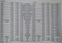
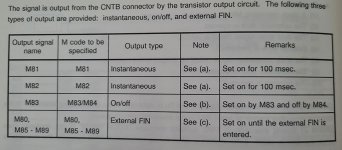
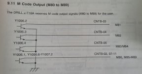
I studied the operator’s manual and found out that there should be M81-M89 for these external outputs. M83 On / M84 Off would be ideal, but it seems that connector is populated. TB2-05 and TB2-06 had wire going somewhere printed K63. I assume this TB2 is the correct terminal block as I didn't find any TB1.. So if I had interpreted this correctly M81 and M82 would be available as TB2-03 and TB2-04 are empty in terminal block. However these seem to be 0.1 second pulse only. That might be enough, as I only need quick blow of air from the magnetic valve.

So the question is, how much current can these M81 and M82 drain? Am I safe if I connect the +24VDC from eg. terminal block #25 to solenoid valve and the other lead to terminal block #3 and of course fly back diode to the coil?

I assume that the M80 is so that it is on as long as terminal block TB2-69 receive signal? Ground or +24VDC?

Pictures of the pages about these outputs attached.

terminal_block_layout.jpgterminal_block_definition.jpgext_out_definition.jpgCircuit_diagram.jpg
 
I don’t have any direct experience with your vintage of robodrill, but i know from the robodrill MATE’s to present day there is an I/O bored with open X&Y addresses in the upper right hand of the electrical cabinet. These X&Y addresses can be configured to the users specifications(Mcodes)thru the Quick NC screen under External I/F.
If you find that this I/O board & external I/F is available on your machine I can help walk you thru setting up your solenoid & tieing to an Mcode.


Back
Top