Copying... Done!
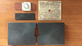
Before copying i did several investigations of what this box should do and how, in order to test it well before inserting to the machine.
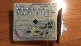
Briefly saying, this is 3 phases reversing contactor for the 380V AC motor, in this machine it is driving colump (head) up and down. It has 3 wires for 380V input, 3 wires to the motor, 2 wires for +24V and GND, and 1 wire - when 24V applied it is enabeling motor to one direction, another 1 wire - when 24V present there - motor is rotating in another direction. When 24V is present on both inputs - motor stops immediately. And most interesting for me was a purpose of one last wire "6" on schematic. On simulation, and later verified on my PCB, there is always nothing (0V), but each time after motor disabling there is a pulse of about 1sec of 24V. Hm... as I guessed and then discovered on the column motor there is built-in brake which is connected to this wire. So actually this is a break signal which is breaking motor immediately after input driving signal is disappearing ( together with disabling of voltage to the motor of course).
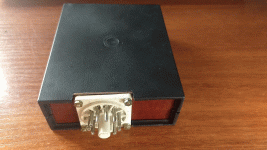
But this storry would not be so interesting without one more problem which I had with it... When i first time tried to insert my unlicensed copy of orange box ( I selected black box, I hope nobody will guess ), nothing happened, nothing was moving at all, and each time I tried i was receiving M504 error on the screen. After some time of suffering with PLC source code, I discovered that this error is appearing after some timeout. Time start when we press a button to drive column. And I was receiving this error almost instantly. Hm.... Next question was how much time we have? And I found answer - it is defined in machine parameter MP194. Its value multiplied by 20ms is a value if seconds of delay. And when I looked to my MP194 value ( i have a sheet of paper with parameters which was inside control box) - it was 0. So I had 0 second timeout to allow motor to drive anywhere... Nice... I've changed it to 2000 (=40sec) and ... and.. it start working just fine!!!! I was extremely glad, I spend so much time and efforts with this problem ( there was another story with hydraulic clamp) and finally it is working! During all my debugging of this issue I realized how really complex it is designed, but in the same time so clever, so many small details which were taken in account, these engineers put piece of their soul to this machine.
Many thanks to jz79, without your photos and efforts this would not be possible.
Before copying i did several investigations of what this box should do and how, in order to test it well before inserting to the machine.
Briefly saying, this is 3 phases reversing contactor for the 380V AC motor, in this machine it is driving colump (head) up and down. It has 3 wires for 380V input, 3 wires to the motor, 2 wires for +24V and GND, and 1 wire - when 24V applied it is enabeling motor to one direction, another 1 wire - when 24V present there - motor is rotating in another direction. When 24V is present on both inputs - motor stops immediately. And most interesting for me was a purpose of one last wire "6" on schematic. On simulation, and later verified on my PCB, there is always nothing (0V), but each time after motor disabling there is a pulse of about 1sec of 24V. Hm... as I guessed and then discovered on the column motor there is built-in brake which is connected to this wire. So actually this is a break signal which is breaking motor immediately after input driving signal is disappearing ( together with disabling of voltage to the motor of course).
But this storry would not be so interesting without one more problem which I had with it... When i first time tried to insert my unlicensed copy of orange box ( I selected black box, I hope nobody will guess
), nothing happened, nothing was moving at all, and each time I tried i was receiving M504 error on the screen. After some time of suffering with PLC source code, I discovered that this error is appearing after some timeout. Time start when we press a button to drive column. And I was receiving this error almost instantly. Hm.... Next question was how much time we have? And I found answer - it is defined in machine parameter MP194. Its value multiplied by 20ms is a value if seconds of delay. And when I looked to my MP194 value ( i have a sheet of paper with parameters which was inside control box) - it was 0. So I had 0 second timeout to allow motor to drive anywhere... Nice... I've changed it to 2000 (=40sec) and ... and.. it start working just fine!!!! I was extremely glad, I spend so much time and efforts with this problem ( there was another story with hydraulic clamp) and finally it is working! During all my debugging of this issue I realized how really complex it is designed, but in the same time so clever, so many small details which were taken in account, these engineers put piece of their soul to this machine.Many thanks to jz79, without your photos and efforts this would not be possible.
Attachments
-
 IMG_20220603_222655932.gif872.2 KB · Views: 6
 -
 HVBV_sch1_2022.JPG188.6 KB · Views: 7
 -
 IMG_20220605_191458085.gif892 KB · Views: 8
 -
 IMG_20220605_190914671.gif989.8 KB · Views: 7
 -
 IMG_20220605_190322676.gif755.8 KB · Views: 7
 -
 IMG_20220604_162609899.gif986 KB · Views: 6
 -
 IMG_20220604_162520153.gif930 KB · Views: 4
 -
 IMG_20220604_162447156.gif943.6 KB · Views: 5
 -
 IMG_20220604_162351553.gif894.3 KB · Views: 5
 -
 IMG_20220604_021946755.gif866.6 KB · Views: 6


