Nerdlinger
Stainless
- Joined
- Aug 10, 2013
- Location
- Chicago, IL
Hi Everyone,
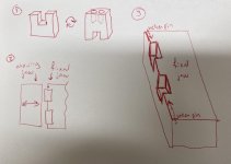
Please see the attached pic. I am reviewing the process we use to make a part that looks like "1" (blank is about 1" X 1.5" X 2" long 4140.) I want to do it in two ops...op one is to face and drill the two holes, flip for op two and face and mill the slot. "2" shows a top view of how I want to mill out pockets in the fixed jaw and clamp with the moving jaw. (We have Kurt hydraulic vices with the "carvlock" machinable cast iron jaws.) "3" shows a weak isometric view of the fixed jaw (only op 1 shown...it's a double vice so op 2 would be largely mirrored from what is shown in my sketch.) I will slide the parts in the pocket from the top until it bottoms out and then the velier pins will push them towards the middle of the fixed jaw. So the parts will now be DOWN and sprung towards each other. Then the moving jaw will clamp against the flat back wall.
HERE'S MY QUESTIONS:
1. The parts are saw cut so the outside surfaces of the blank that make contact with the WALLS of the vice pocket are cold drawn drawn and the top surface that gets faced and the bottom surface that rests on the FLOOR of the vice pocket are saw cut. Since those saw-cut ends will not be flat (at least not for op 1) I am thinking about putting a rounded rest button in the center of the floor of the vice pocket. Does that make sense? It seems like it would make it less "tippy" during the drill op with its downward force (5/8" drill.)
2. Should I just leave the wall opposite the moving jaw clamp flat or should I put three rest buttons to "define the plane?" (I am going to put serrated gripper pads on the moving jaw to help with grip, FYI.)
3. Despite previous failures I am going to machine the outside profile of the part on both ops and try my darnedest to match up those mismatch lines. It is just a skim cut to forego a hand grinding op and I am hoping a rigid fixed jaw will help make that possible. If I cannot get it good enough (<.001") I want to try modifying a 1/2" end mill down .005" on the diameter very gradually beyond the necessary DOC instead of a square end or even a large corner radius em. Has anyone every tried that?? I am hoping it take any mismatch and blend them real nice.
Thank you for your help!


