Dalmatiangirl:
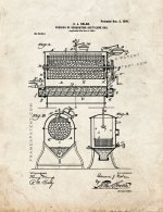
With no disrespect, the similarities between the tank in the OP's photos and the patent drawing of the acetylene generator seem superficial. The tank in the OP's drawing lacks features on the acetylene generator: no charging port/closure for loading in calcium carbide, no weighted safety valve or weighted pressure regulating valve, and the acetylene generator has a 'hopper bottom' with screw conveyor (likely to clean out the spent carbide slurry).
Your posting of the patent drawing has me studying it at length. Home/farm acetylene generators for lighting were common, but I had never seen one or even detailed drawings of one. I've seen welding acetylene generators, but these were always vertical units, usually with a glass chamber on top. Our synagogue building was built in 1920, in a small village in NY State. At the time, there was neither grid power, no running water, no inside plumbing and no central heat. I am 'the building committee", entrusted to look after the maintenance and upkeep of the building. I've been in this position for somewhere around twenty (20) years, so got familiar with the building. It is built to the plans for a simple country church, which was what the local builder knew. There are open heavy wood trusses supporting the roof. Over the years, the synagogue got electricity, town water, and inside plumbing. We even added Mitsubishi 'split system' HVAC a few years back. There is a small attic over the social area of the building, and I've been up there a few times. When I first went up to that attic, I found these old gas light fixtures with shades made like stained glass work, by soldering lead channel strips to hold the glass parts in place. These fixtures had gas jets in them. I was able to look at the roof trusses from the attic thru a ventilation louver and saw 1/2" screwed steel pipe run on the tops of the bottom chords of each truss, not visible from inside the synagogue. This was the gas distribution piping.
The only plausible source of illuminating gas would have been an acetylene generator, long gone and no one left alive who knew anything about it. I've wondered for the past 20 + years what an on-site acetylene generator for small buildings would have looked like. Thank you for posting the patent drawings.
Acetylene lights used a 'full rich' acetylene flame, no air mixer on the burners. Straight gas jets. Most of us have used oxyacetylene torches in one way or another for most of our working lives. We have all had the experience of cracking the acetylene valve and lighting a 'full rich flame' on a torch. Soot and soot particles are in the air, and the flame is luminous but little heat. When we babbitt bearings, I often 'smoke up' the mandrel or shaft using an oxyacetylene torch with the full rich flame to coat the mandrel or shaft with 'lampblack' (carbon soot). Knowing that from experience, I often wondered what kind of mess the acetylene lighting created, how often the jets had to be cleaned of accumulated carbon/soot and how often the lampshades or reflectors had to be cleaned, and how much black soot wound up on the ceilings.
Early automobiles and even motorcycles and bicycles used carbide/water acetylene generators or self-contained lamps. As a kid, I had a 'carbide bug'- a brass cap lamp that miners or spelunkers would use. The bottom container took some crushed carbide (aka "lamp grade carbide", in a green can from "Shawingan" or similar name). The top container filled with water. Open a small valve with graduated thumb tab and the water began trickling down into the carbide. A 'cigarette lighter' type spark igniter (knurled steel wheel and spring loaded lighter flint) was set in the reflector. The 'bug' threw a bright light and was a handy light if you had carbide and water.
About 1985, I was on a job and we had some 'pipeliners' (welders who had their own 'rig trucks' to weld field run piping) on the project. One older pipeliner told me he had been raised on a small family farm, and they had an acetylene generator for lighting. He recalled that the spent carbide/water was scooped out of the generator and used to whitewash the inside of their milking barn, milk house, and the bases of the trunks of all their fruit trees. I never asked him about how the generator was designed. He did say he did not like the job of mucking out the spent carbide slurry, recalling it stank.
 3794C51D-18B0-47F8-9D5A-A8B872CD5E28.jpeg29.5 KB · Views: 108
 C0E6643B-7BC3-49CE-BCDB-1B0B8597D2E9.jpeg18.6 KB · Views: 108
 AD84218C-BEF7-4464-9020-D2506CF810CF.jpeg31.8 KB · Views: 116
 3A58D924-9690-4DFA-A24E-46D359A0E59E.jpeg19.3 KB · Views: 108
 97E8E687-8EF4-44C7-BD7B-00B890CDEBB6.jpeg30.1 KB · Views: 107
 86F6008E-F852-4944-92DD-4D4516232C70.jpeg27.2 KB · Views: 109