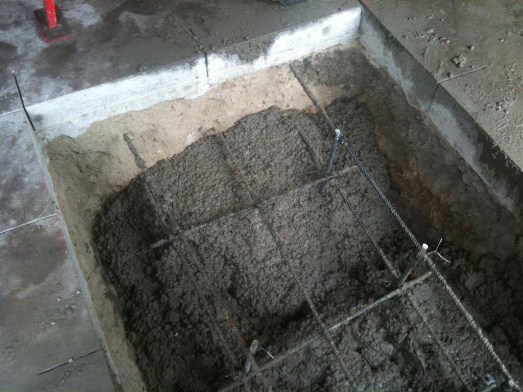
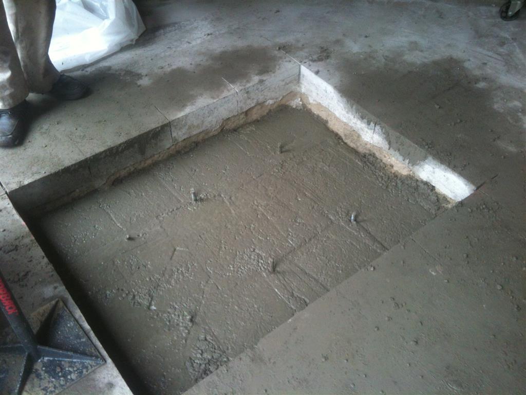
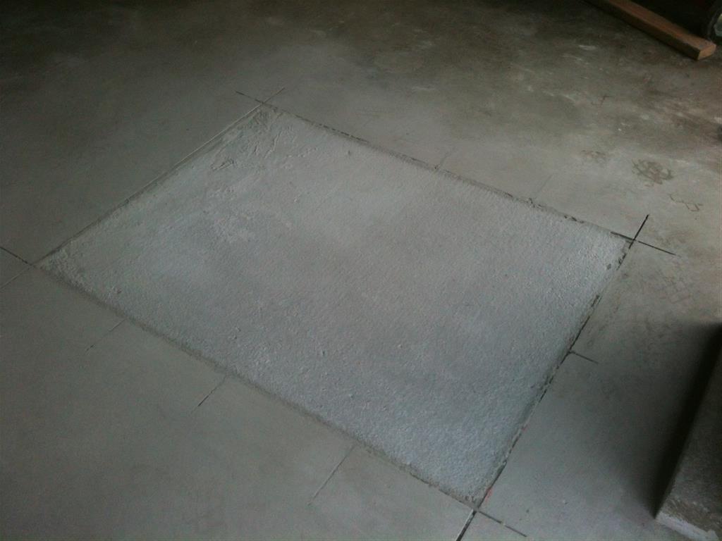
The other thing that probably should have been done on the hammer foundation was to put a layer of number 2 crushed stone at the bottom of the hole. This layer would be about 6" deep. It was always "design practice" on machinery and structural foundations to put a bed of number 2 crushed stone down and rake it off level before placing the concrete. This was done for drainage and to help with distributing the load of the foundation on the excavated surface of the soil.
Another thing that used to be done in larger hammer foundations and on some stamping press foundations was to put down a bed of either creosote impregnated oak or tar-coated cork blocking. This was laid at the bottom of the excavation for the foundation. The sides of the foundations for large hammers and stamping presses were also "jacketed" with either creosote=impregnated hardwood or tar-coated cork blocking. The purpose was to provide complete isolation of the foundation from the subgrade soil as well as the surrounding building. The foundations for hammers and other machinery with impact loads were designed as "inertia blocks". There was enough mass in the foundation to fully absorb the energy of the hammer or press's impact (or what portion of it that did not go into the work being forged or stamped). Older editions of "Machinery's Handbook" have some information on foundations for forging hammers.
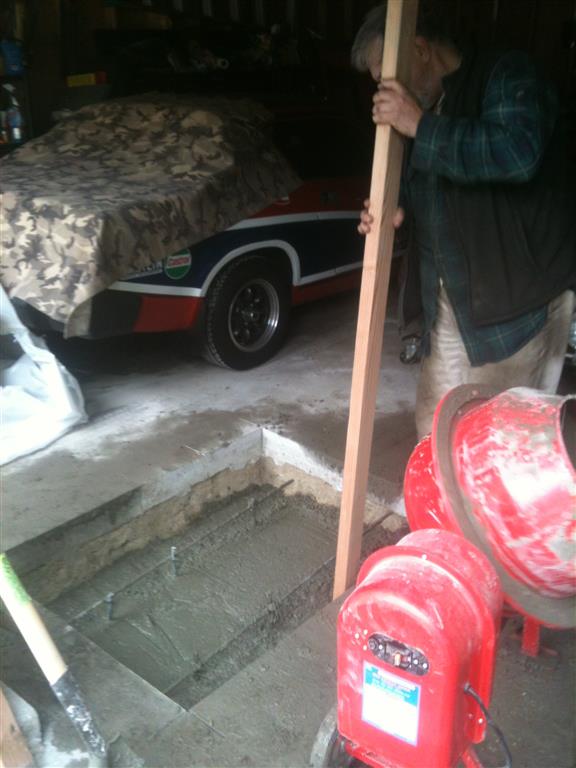
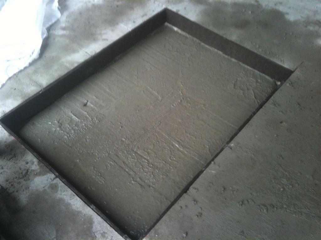
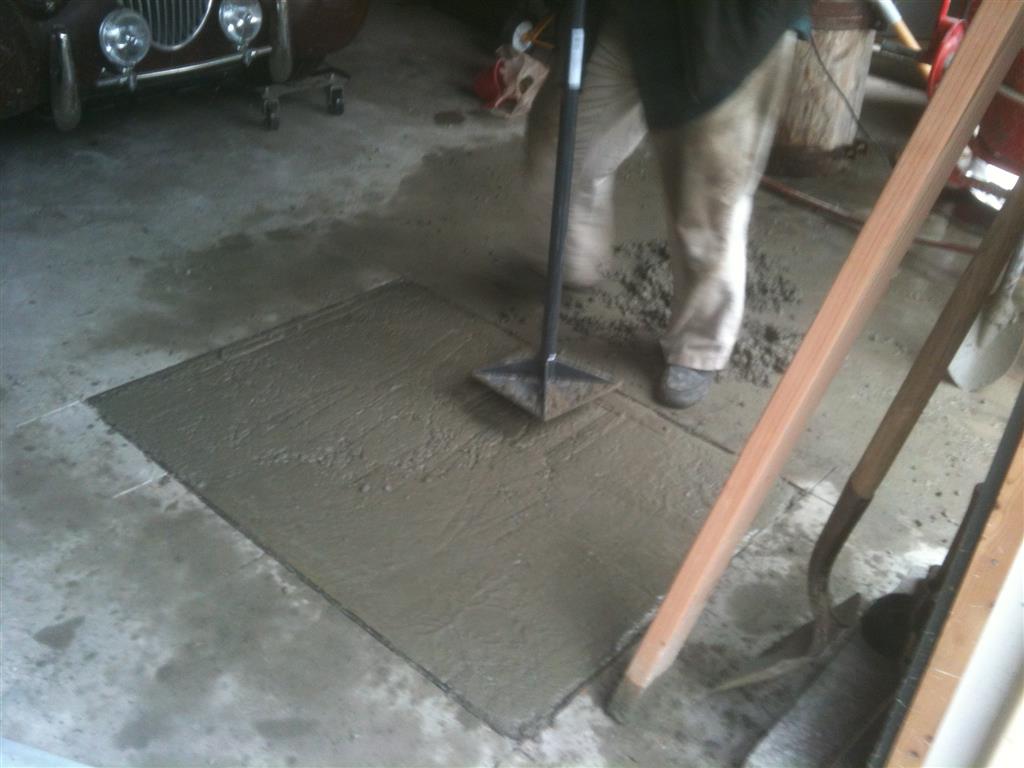
I'd still go with a 3" to 3 1/2" slump for concrete going into a hammer foundation. Place the concrete in "lifts" of maybe 6" if you are mixing it on site, and rod the concrete with steel rods to get it to compact into a homogeneous mass. The use of the vibrator does compact the concrete and work up any air pockets. Unfortunately, many laborers tend to use the vibrators to move the concrete in the forms. On big pours with lots of tight mats or rebar and lots of imbed items (such as anchor bolts, piping, grounding cable mats, etc), and with blockouts (openings formed in the concrete with formwork), a stiff mix of concrete does not want to just drop and fill the forms. This is when the laborers up on top of the forms start working the vibrators (known in the trade as bull pricks). A good crew will keep the vibrators moving steadily, either working them up and down, or moving them along in the forms. Letting the vibrators stand too long in any one spot in the concrete causes "segregation of the aggregates". Fancy term for having all the crushed stone settle to the bottom of the concrete in that location.
I've worked jobs where we placed 1200 to 1500 yards of concrete in one continuous pour on hydroelectric plant work. I've worked jobs where we used concrete buckets run off the cranes, and I've worked jobs where we used the concrete pumps. Probably the wildest way of placing concrete that I've been around is "Tremie' placement". We were putting in caisson foundations for some power transmission (aka "high line" or "power line") structures. The right of way for a power transmission line zig zags based on getting the right of way from landowners, avoiding certain things like towns and wetlands, and it follows the terrain. As a result, many of the foundations get put in up on mountainsides or out in the woods. A caisson foundation is augered into the earth, and is about 12 feet in diameter and can be as much as 40 feet deep. Into this hole goes a sectional steel shell to hold the walls from caving in, and then a prefabbed rebar cage made of number 12 bar ( 1 1/2") and number 16 (2") bar is set in the hole. In the middle goes a prefabbed anchor bolt assembly with all the bolts welded to support/spacer bars. Needless to say, this is a massive pour to deal with, often in rough and remote locations. Naturally, if you open a hole 40 feet deep, you stand a good chance of ground water filling it. When that happens, it is time for the "Tremie' pour". No effort is made to unwater the hole. The Tremie pour is done with a steel pipe about 12" inner diameter that is assembled with mechanical joints and lowered to the bottom of the hole. At the top of the pipe, there is a pouring funnel or hopper for the concrete. A fancy Tremie pour setup will have a steel gate at the bottom of the pipe, worked by cable from up on top. We never had anything that fancy. We used to get a basket ball or soccer ball and inflate it so it plugged the bottom of the Tremie pipe. The Tremi pipe was lowered down the hole with a crane. When the Tremie pipe was in place and chained off, the concrete trucks started mixing and placing. We'd have the trucks lined up and timing was everything. Due to the remoteness of the sites, we'd have the trucks batch out dry from the batch plant. Water was introduced to the mix at the site of the pour. We'd test slump, air entrainment, mix temperature, water temp on the trucks, and number of turns. Tremie concrete is a stiff mix. It has to be, since it is dropping down the Tremie pipe and then going under water. The concrete went down the Tremie pipe, and pushed out the ball (which came bobbing up to the surface of the water). The concrete was placed continuously into the Tremie pipe, and it displaced the water in the hole, causing it to rise up and out from the top of the hole. The steel casing in the hole was usually pulled when the concrete was fairly high in the hole and the water had been displaced. At that point, a set of steel ring forms were set at the grade line to form the extension of the foundation above the grade line. It was a simple and ingenious method of placing concrete, and we used it a lot for flooded excavations.
I visited a water tunnel job that was about 600 ft below the elevation of the ground above. Went down in a mine hoist cage, pretty much like in a coal mine. The water tunnel (for NYC) was huge, and was being excavated in solid rock. Once the rock excavation and roof bolting was done, the tunnel was being line with concrete. The concrete was mixed up at the surface at the head of the shaft by an on site batch plant. A large steel pipe descended vertically in the shaft, all the way to the bottom. At the bottom of the shaft, there was a hopper to receive the concrete, which was the supply to a concrete pump. The way the concrete was moved was quite interesting. A pumpable mix of concrete with admixtures to retard set time and increase workability and eliminate voids was dumped down this pipe. The first few yards of concrete were considered as "cushion concrete". The first few yards were allowed to sit at the bottom of the hopper, and the rest of the batch was what made it into the pump. The reason was to give the concrete a cushion so the aggregate did not all wind up at the bottom of the hopper. The pump moved the concrete out through pipes (slick lines) over what seemed impossibly long distances to where it was being placed to line the tunnel. The first few yards of each batch were sent up to the surface along with excavated rock and other debris. The tunnel and valve chamber were so big that large rubber tired articulated loaders and steel tracked dozers and loaders were in use in it. Those were lowered down the shaft in semi-disassembled condition and re-assembled at the bottom. Good diesel exhaust filters and catalytic converters, along with good ventilation allowed the diesel equipment to run in the tunnels. We walked something like 3 miles one way in the tunnel they were working on, crossing from the Bronx into Westchester County to get to the heading where the liner concrete was being placed. Interesting work, but not a job I'd care to be on.