dgfoster
Diamond
- Joined
- Jun 14, 2008
- Location
- Bellingham, WA
I had a little time in the airport yesterday so I pulled out the computer to pass the time.
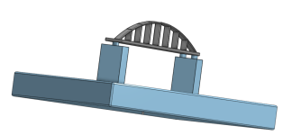
I did make the initial setup in my shop as schematically drawn in the first two images. The base is a granite surface plate that is flat (not really important for this use) and stable---very important. On that are 2-4-6 blocks that I ground a few years back to be very flat, parallel, and square though the main important feature for this use is flatness---no rocking whatsoever. Then the three pivot points are as shown. And on top of all that a raw, thermally- stress-relieved 36" Featehrweight Camelback that I milled at each end and centrally where the indicator will make contact. I made a small "puck" 1/2 in diameter and centrally relieved to sit on top of the round probe tip so that there was better/more reliable bearing of the tip on the underside of the SE.
I have not really had time to make certain the pivot points are going to be rock solid. If they are not, I have other plans for support. But, my goal is to have an extremely solid setup that is not subject to disturbance from minor vibration (likeing walking on the concrete slab or traffic passing by on the road 75 feet away.)


THe checker probe will be placed on a fairly robust base I made a couple years to hold a tenths-indicating electronic Federal indicator. Happily its probe barrel and the barrel of the Mitutoyo are both nominally .375 OD. It is convenient to adjust the probe stick-out in this base and the base itself is heavy and very flat so it does not rock. It will slide under the SE in a way similar to it as shown in the photo below.

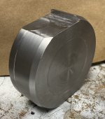
The base of the support top side.

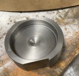
Underside centrally relieved.

A couple years ago I posted a video of this indicator/base setup being used to look at the flatness of one of my 18" prisms.
My plan is to get everything setup as shown but with a 5 gallon bucket resting in a saddle on the midportion of the SE. Then measure accurately the position of the SE undersurface and confirm that the mount is stable. Then fill the bucket with 25 or 30 pounds of water and measure deflection which I expect to be on the order of .0001" Then, I'll leave the weight in place for varying periods of time. At the end of a given trial period I will release the water via a stop on an attached plastic tube. I figure using water to load and unload is very unlikely to inadvertently side load the setup and introduce error. I will be looking to see if there is any persistent deflection ("set") after loading. Based on Rich's description (which was not really specific as to the number of days elapsed) in about post 30 above, a period of a few days should be enough to make a set occur if one to occur at all. I'll try to keep the setup going for as long as practical to make observations.
Using the same setup, I can see what distortion of the SE occurs with bare-hand contact with the bow of the SE so that a quantitative assessment of just how much disturbance occurs related to local warming of the bow. Will this be worse of better than that of the angle plate shown in another thread. Just after setting up, I did a couple of very quick trials of hand contact and was surprised to see that it look like deflection of the SE base was slower than that of the angle plate. We'll see if that holds.
Finally, I'll also be able to see how much deflection occurs from simple loading. I have measured that previously with equipment ten times less sensitive than the checker Carbidebob gave me.
Temperature variation of the garage will be a potential source of error, of course. But, if you notice we have basically 3 seel columns that are parallel reaching up to the SE sole---the two block/pivots located at the ends of the SE and the probe support. So, slow temp variations will be more or less equally affecting those members. Happily, this is a time in the PNW where day to night temperature variation is relatively mild. I may well set up a standard near the SE that will be of solid steel construction and to which measurements of the plate-to-sole distance can be compared to validate stability of the measuring device.
I am away from the shop for a week. So, I probably will have little to add to this thread for a week. THe exception being if I find relevant information in ASU's Polytechnic library as they hold a copy of ASM Handbook Volume 1 which delves into cast iron. I recently picked up a couple other volumes dealing with machining and casting. Though the information is not totally current, the basics of machining, casting metal, steel, and cast iron have not really changed fundamentally. So, I am learning the books are a concentrated trove of interesting facts.
I do hope people with constructive criticism will not hesitate to chime in. I'd like to hear opinions on how the setup could be modified to do a better job.
Denis
I did make the initial setup in my shop as schematically drawn in the first two images. The base is a granite surface plate that is flat (not really important for this use) and stable---very important. On that are 2-4-6 blocks that I ground a few years back to be very flat, parallel, and square though the main important feature for this use is flatness---no rocking whatsoever. Then the three pivot points are as shown. And on top of all that a raw, thermally- stress-relieved 36" Featehrweight Camelback that I milled at each end and centrally where the indicator will make contact. I made a small "puck" 1/2 in diameter and centrally relieved to sit on top of the round probe tip so that there was better/more reliable bearing of the tip on the underside of the SE.
I have not really had time to make certain the pivot points are going to be rock solid. If they are not, I have other plans for support. But, my goal is to have an extremely solid setup that is not subject to disturbance from minor vibration (likeing walking on the concrete slab or traffic passing by on the road 75 feet away.)
THe checker probe will be placed on a fairly robust base I made a couple years to hold a tenths-indicating electronic Federal indicator. Happily its probe barrel and the barrel of the Mitutoyo are both nominally .375 OD. It is convenient to adjust the probe stick-out in this base and the base itself is heavy and very flat so it does not rock. It will slide under the SE in a way similar to it as shown in the photo below.
The base of the support top side.
Underside centrally relieved.
A couple years ago I posted a video of this indicator/base setup being used to look at the flatness of one of my 18" prisms.
My plan is to get everything setup as shown but with a 5 gallon bucket resting in a saddle on the midportion of the SE. Then measure accurately the position of the SE undersurface and confirm that the mount is stable. Then fill the bucket with 25 or 30 pounds of water and measure deflection which I expect to be on the order of .0001" Then, I'll leave the weight in place for varying periods of time. At the end of a given trial period I will release the water via a stop on an attached plastic tube. I figure using water to load and unload is very unlikely to inadvertently side load the setup and introduce error. I will be looking to see if there is any persistent deflection ("set") after loading. Based on Rich's description (which was not really specific as to the number of days elapsed) in about post 30 above, a period of a few days should be enough to make a set occur if one to occur at all. I'll try to keep the setup going for as long as practical to make observations.
Using the same setup, I can see what distortion of the SE occurs with bare-hand contact with the bow of the SE so that a quantitative assessment of just how much disturbance occurs related to local warming of the bow. Will this be worse of better than that of the angle plate shown in another thread. Just after setting up, I did a couple of very quick trials of hand contact and was surprised to see that it look like deflection of the SE base was slower than that of the angle plate. We'll see if that holds.
Finally, I'll also be able to see how much deflection occurs from simple loading. I have measured that previously with equipment ten times less sensitive than the checker Carbidebob gave me.
Temperature variation of the garage will be a potential source of error, of course. But, if you notice we have basically 3 seel columns that are parallel reaching up to the SE sole---the two block/pivots located at the ends of the SE and the probe support. So, slow temp variations will be more or less equally affecting those members. Happily, this is a time in the PNW where day to night temperature variation is relatively mild. I may well set up a standard near the SE that will be of solid steel construction and to which measurements of the plate-to-sole distance can be compared to validate stability of the measuring device.
I am away from the shop for a week. So, I probably will have little to add to this thread for a week. THe exception being if I find relevant information in ASU's Polytechnic library as they hold a copy of ASM Handbook Volume 1 which delves into cast iron. I recently picked up a couple other volumes dealing with machining and casting. Though the information is not totally current, the basics of machining, casting metal, steel, and cast iron have not really changed fundamentally. So, I am learning the books are a concentrated trove of interesting facts.
I do hope people with constructive criticism will not hesitate to chime in. I'd like to hear opinions on how the setup could be modified to do a better job.
Denis
Attachments


Last edited:
