What's new
What's new

FP 1 Dismantle

No, I did not actually. I wanted to manufacture them because I am really bad at cutting threads on the lathe and looking for excuses to practice.

PS. Just checked out of curiosity, it costs around 3€ M20x1

Poyraz
 
Correction, it is m18x1 and I could not find off the shelf item with that specs, they have 17x1 and next size is 20x1. I made like 4 of them, in case similar size is used elsewhere on the machine.
 
So, most of the problems are solved. I could not clean it as thorough as I wanted but don't have time to go any deeper.

Any suggestions on how to push the wicks through oil channels? Also, to y axis oil plate had some sheet of paper looking thing to stop oil from leaking, is it OK if I use gasket sealant?

Cheers,
Poyraz
 
Also finished the design and printing of splash guard,I'll do a test fit, if its alright, will be sent for casting.

View attachment 325853
View attachment 325854View attachment 325855

Hey if it works, don't forget your american brethren who have this exact part broken in this exact same way that could use a replacement :D

I swear your mill is in the same condition mine was in. I did a pretty thorough degrease and re-oil when I had it apart.
 
It did fit in place, radius of the part could be smidge smaller but can't complain. I gave it couple of coats of PU paint and will confirm the results during the weekend. And I can share the part with you once I believe its ok.

I've been also degreasing and oiling it along the way. Also got rid of the table feed and coolant pump mechanisms since I wont be using them. I have the change gear feed model and I do not have the change gears. Planning to place there a 12NM servo that I have laying around or a geared AC motor. Meaning I'll be able to feed also while motor is in reverse(not sure if it will have any use.)
 
I 3d printed it since some already indicated it does not have to be made of metal. I also painted it with couple of coats of PU paint should be just fine. I will share it on thingiverse since you are already the second person needing it. With slight change can be also used as a template for casting. Franz Singer had it in stock but too expensive for my taste, if you say you need it out of alu get in touch with him.
 
This seems like a quite a big effort for such simple part, its not as detailed as the skull so simple sand casting would probably be ok.


PS. I ended up watching several other videos of that dude, pretty cool :D
 
Sorry for the late reply, I had to modify the part a bit and printing and tryouts takes time :) but final version fits perfectly.

STL file can be found below and if someone is interested in the fusion360 file for further modifications, please send me a dm. I printed it out of PLA and coated with PU paint. %30 infil

PS. I miss read the manual regarding to oil where it points about how much oil you need in the main gearbox train. It needed approx 1.5 liters and I put around 3 :D then next day I found the base of the machine flooded in oil. Do not do it! :D At least machine is oiled thoroughly!!!

View attachment oil splash guard v1.zip
 
Next day I found the base of the machine flooded in oil.

Even without such mishaps, the base of the machine will always be oily, because the oil from the Z ways and the support quickly finds its way to the base. I've given up on keeping that area clean.
 
Even without such mishaps, the base of the machine will always be oily, because the oil from the Z ways and the support quickly finds its way to the base. I've given up on keeping that area clean.


I keep some folded shop towels just under the bottom of the "Z" box ways on my FP2 & 3...
Change out when oil soaked...remove if using coolant (which i seldom do)

They got smarter with the FP-NC's...There the oil off the "Z" ways is caught in little plastic catch trays that direct the oil back into a channel that runs to the rear of the machine under the main casting.
From there the oil is collected in a basin at the rear of the main base (cast in) ...Works pretty well....I have my NC's set with the from slightly high (out of level front to back) to aide i coolant and tramp oil drainage...

Cheers Ross
 
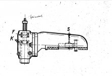
I cleaned the oil from the base casting, run the machine at 750 RPM as recommended and seems to be fine. Only thing left is to clean the vertical head and attach it. There are tons of posts about the oil topic, but I still don't get how the bevel gears gets lubricated, oil nipple(K) and grease cap(F) on the front of the spindle are for the spindle, neither oil nor grease will reach there, is it through the S oil point above the vertical head?

2020-11-26_14-23-41.jpg


Second question, any idea what is the thread size on the base of the machine intended for the legs/pegs/stands (whatever they are called) I have mines quite rusty and filled, would like to rethread them, seemed to be m16 but not sure about the pitch if it's standart or not, also I definitely need to drill the base on the front to make a drainage hole or something.

Cheers Poyraz
 
I still don't get how the bevel gears gets lubricated, oil nipple(K) and grease cap(F) on the front of the spindle are for the spindle, neither oil nor grease will reach there, is it through the S oil point above the vertical head?

Grease the bevel gears during assembly.
 
I cleaned the oil from the base casting, run the machine at 750 RPM as recommended and seems to be fine. Only thing left is to clean the vertical head and attach it. There are tons of posts about the oil topic, but I still don't get how the bevel gears gets lubricated, oil nipple(K) and grease cap(F) on the front of the spindle are for the spindle, neither oil nor grease will reach there, is it through the S oil point above the vertical head?

View attachment 333647

Cheers Poyraz

The S oil point is to lube the plain bearing at the back of that shaft.
 
The holes in the base for bolting it down are clearance for M16 (about 17.2 on mine). They were never threaded as it used to be the norm to bolt machines to the floor after leveling on shims. I just installed my FP1 and used leveling feet with hard rubber pads (don't use soft rubber feet). The ones I could get locally were only M12 so I bought four M16 x150 bolts and drilled and tapped the head end M12 to screw the feet into. It seems to work well so far and the added 1 1/2" height makes it better to use as I don't have to stoop as much. If you have a look on Franz Singer site he sell a set of feet for the FPs that have an M16 stud with a sperical end and cast plates with a matching socket. It would be easy to make something up using M16 studding and roled plate if you wanted.
 
Thanks a lot, since the holes are not very clean and I did not want to drill them to clean or anything like that I left them like that till I figure out if the inner surface is threaded. Since I know now, I can go ahead and clean them and make some pads!
 
Machine is finally up and running, still have to do the gibs adjustments though.

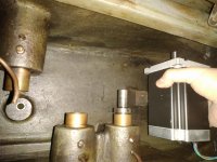
Since I gutted the table feed, I started thinking on how to come up with a way to attach a 14nm NEMA34 motor in there.

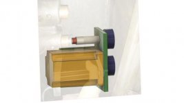
Shaft is too short and motor is taking quite some space in there. I thought of something like this in the images below, extend the shaft, support the motor and the extended shaft with a bracket(a bearing ofc to keep the load of the extension off the main shaft). And user timing pulleys/belts for transferring the motion from one shaft to another.

There are two threaded holes where the coolant pump used to be, they should be enough the hold the bracket, if needed I can place a support somewhere under the bracket on the opposite side which can rest on the base casting.

Let me know if you see any flaws in my design.

Cheers,
Poyraz
IMG_20220116_120944.jpg
bracket v2.jpg
bracket v2_1.jpg


Back
Top