What's new
What's new

Full tear down and Rebuild of a 10EE Round Dial

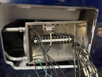
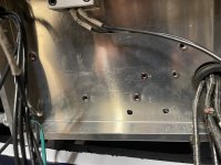
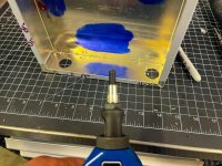
With the holes drilled I could then install the rivetnuts. These work just like regular rivets except they use threaded mandrills.
Junctionboxcomponets5.jpg
All of the rivet nuts installed.
Junctionboxcomponets6.jpg
These allow me to use standard screws to install all of the components and if anything ever needs to get swapped out, it will be easy.

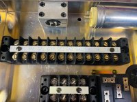
I was a bit concerned about the longevity of using printed labels for the terminal blocks. So I used a carbide scribe and etched each label. I then rub dykem on it, and then immediately ripped clean with alcohol. This left an etched and dyed surface that I won't have to worry about the label text wiping off or the labels falling off.
Junctionboxcomponets7.jpg
Not wanting to stare at my chicken scratches I then covered them with labels.
Junctionboxcomponets8.jpg
[FONT=interstate, sans-serif]And its ready to get installed in the lathe. Time for a beer or 3.[/FONT]
 
Lower cover is on. The alignment to the lathe casting is damn perfect in the front, and very close with the exception of one section on the back. ...

Ok, lets see how it looks with the upper cover ...
...
... they dont line up.
View attachment 348146
I'm curious if this lower cover which is off of a newer machine, is built to slightly different depth dimensions than the original cover. ...
View attachment 348147
...
The stamped number next to the measuring tape is the serial number of the donor machine: 42801. That means it came from a square-dial machine built in 1958. As far as I know, all motor/generator and WiaD (Works in a Drawer) drive machines used the same basic pattern for the base casting, with relatively minor changes made to the pattern for the piggy-back exciter and WiaD drives. I would think that the donor cover should fit.

However, the lower drive cover casting was changed at least three, probably four times:

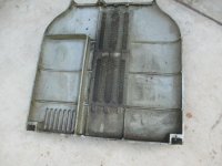
Here's the cover from my 1943 round dial, casting number EE-2?33 (the second digit is unreadable):
EE24315 IMG_4925 lower drive cover casting EE 2_33.jpg
This casting is weak and tends to crack vertically down the middle. Based on the partial casting number, this is not the same cover used on Sundstrand-drive machines, so it's at least the second generation of cover.

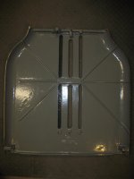
Here is later model lower drive cover, probably from an MG or WiaD square-dial, casting number EE-2427:
ebay 164256732021 09 casting number EE-2427.jpg
I suspect that this is what you have. Note how the ribbing has been changed to strengthen the cover.

Here is the cover from a modular-drive 10EE, casting EE-3437:
ebay 164256732544 07.jpg
Note the vents in the lower-left corner and the ribs that line up with the electronics enclosure in the (redesigned) modular-drive base.

I bet that lower-drive covers from round-dial 10EEs are hard to find, simply because so many of them got broken in two. Mine was cracked through both center vent holes, with only the rib at the very top holding the halves together.

Cal
 
. As far as I know, all motor/generator and WiaD (Works in a Drawer) drive machines used the same basic pattern for the base casting, with relatively minor changes made to the pattern for the piggy-back exciter and WiaD drives. I would think that the donor cover should fit.

However, the lower drive cover casting was changed at least three, probably four times:

Here's the cover from my 1943 round dial, casting number EE-2?33 (the second digit is unreadable):
View attachment 348179
This casting is weak and tends to crack vertically down the middle. Based on the partial casting number, this is not the same cover used on Sundstrand-drive machines, so it's at least the second generation of cover.

Here is later model lower drive cover, probably from an MG or WiaD square-dial, casting number EE-2427:
View attachment 348180
I suspect that this is what you have. Note how the ribbing has been changed to strengthen the cover.

Here is the cover from a modular-drive 10EE, casting EE-3437:
View attachment 348181
Note the vents in the lower-left corner and the ribs that line up with the electronics enclosure in the (redesigned) modular-drive base.

I bet that lower-drive covers from round-dial 10EEs are hard to find, simply because so many of them got broken in two. Mine was cracked through both center vent holes, with only the rib at the very top holding the halves together.

Cal

Cal that is super informative.

It seems to me they must have changed the material composition a bit too, as this cover is so light compared to the upper I have, it must be made from a much lighter material given its size. I am very curious if they also changed the depth of the cover, thus needed to fab the dog tabs that hold it on, and the difference in stick out between this cover and the head stock.

I think I will be able to make this work, unless a true round dial series lower cover miraculously appears at a price I can stomach.
 
...

It seems to me they must have changed the material composition a bit too, as this cover is so light compared to the upper I have, it must be made from a much lighter material given its size. ...
My covers are all cast iron, including the trim strips. Check the donor cover with a magnet. If it's non-magnetic, it's likely so sort of aluminum alloy.

Cal
 
My covers are all cast iron, including the trim strips. Check the donor cover with a magnet. If it's non-magnetic, it's likely so sort of aluminum alloy.

Cal
Cal, the donor door is non-magnetic, so its some aluminum alloy, my top cover is cast iron.

I'm liking this forum upgrade. Let me know if these pics show up small now.

The last few weeks have been busy. I got sent down to Mammoth to do one last shoot for the winter with skiing icon Glen Plake. If you saw any ski movies from the 90's you will recognize the hair cut.
image.jpeg
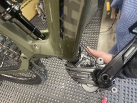
When I got back home, I got a call that my new Transition Repeater Ebike was finally in. This thing is pretty sweet, all carbon, and it actually handles and rides like a true bike, unlike any of the other E-bikes I have been on. Of course I had to do some upgrades to it, right away.
image.jpeg
It's truly amazing what that little motor can do. I can easily get 25 miles and 4K of vert out of a charge with it, and I am pretty sure if I switch to the detuned settings 6K of climbing in a ride is doable. With the motor out, I removed the cables for the seat post and the rear derailleur and set the bike up with a wireless seat post and wireless shifting. I also removed the stock shock and replaced it with a custom tuned coil system by Push out of Colorado.
image.jpeg
image.jpeg
I am still waiting for the fork upgrades to come in, but its already riding really well!

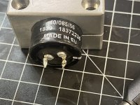
With the new bike setup, its time to get back to the lathe. First thing I needed to do was to solder some leads onto the starting capcitor for the single phase conversions. I picked up this little soldering iron from a recommendation over on Garage Journal a few years ago, and I am pretty impressed with it and like it better than my old Weller ones.
image.jpeg
I first tinned the leads of the capcitor
image.jpeg
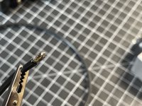
And then used a third hand soldering tool to tin the wire leads.
image.jpeg
I could then use the third hand tool to hold the wire to the capcitor and then solder them together.
image.jpeg
That worked pretty well, but I had more than my fair share of coffee in the am, and had a hard time holding my hand steady. You can see where I accidentally touched the top of the capacitor. Not ideal, but it should be ok.
I then added heat shrink labels to cover the connections.image.jpeg
 
The box then needs to get installed in the machine. Since I am using a wider box than the original, I need to cut the conduit to length.
image.jpeg
Once I determined the proper length, I used this little Lenox pipe cutter.
image.jpeg
I have a whole range of pipe cutters, including some absolutely massive ones, but this little guy tends to get used the most, as it fits into spaces others won't and it seems lately any time I need to fix any plumbing thats the case. With the conduit trimmed to length I could install the box for a test fit.
image.jpeg
And this is where I ran into some problems. When I was determining the layout for the electronics mounts, I was off by just a bit and the rivet nuts are hitting the protrusions on the Motor Generator. Shit! I marked the location where causing the interference and removed the box.
image.jpeg
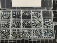
I did some research and found out about these special sheet metal fasteners called PEM nuts or self clenching SWAG nuts. Not wanting to place an order with McMaster for just a handful of fasteners, I ordered an assortment off of amazon, for less than the cost of shipping at McMaster.
image.jpeg
100% pure grade chinesium. I especially like the Warm Tip. Especially after I opened up the package and found out that a child was obviously the one sorting them.
image.jpeg
That was that, and I re-learned a lesson I learned years ago, never buy cheap fasteners off of amazon. So those got sent back. When I was down at our local mom and pop hardware store looking for a better grommet for the box, I found that they actually stocked some of these fasteners in the exact SAE sizes I needed. and they where made in the USA as well.

Here is a comparison shot showing the difference in thickness between these and the rivet nuts. Exactly what I needed.
image.jpeg
Luckily they used the same size hole as the rivet nuts. Typically you would use a special threaded punch and die to install these (the rivet nut gun I have won't do it). Since I am only installing a few of them, I used my arbor press and bench block to press them in.
image.jpeg
That worked super well. I wouldn't want to do 100 of them that way, but for this few it worked great!

For the grommet, I ended up picking up some groove grommeting. (the local hardware store is like a mom and pop version of McMaster, they pretty much have just about everything you could imagine!)
image.jpeg
That worked perfectly for the hole and is much thinner giving me more room for the wires.
image.jpeg
I gotta do some touch up painting on the interior of the lathe from installing the Motor Generator in the am. Once thats dry I will install the junction box finally.
 
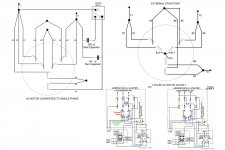
While doing a bit more research into the Steelman method of converting the 3Phase AC motor of the lathes Motor / Generator setup to Single Phase, I found a really good manual on installing Steelman's H-A-S static phase converters... this site does a really good job of describing the steps needed to modify a 3 Phase motor to run on single phase. In this case 240V. I’ve copied a few diagrams and a good portion of the text explaining the conversion and the math from the Steelman site in the next two posts.

The first challenge with this conversion, is you need a 12 wire motor. Problem is most 3Phase AC motors only have 9 leads coming out out it. As is the case with Reliance VS drive this lathe uses. This is shown clearly on it's name plate:
image.jpeg
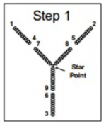
The first step was to take the M/G apart and separate the internal star point, as per this diagram from the Steelman site.
image.pngimage.png
This then gives you 12 leads. The first part of this thread on PM does a good job of describing that process. I documented that full process earlier in this thread. Starting HERE.
image.jpeg
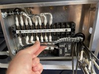
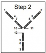
I used an Ohme meter to identify each of the leads as per the diagram in step2 above. With this done, I reinstalled the motor, and then wired the terminal panel. There is a lot of wiring going on in the terminal panel, so I did my best to keep it as organized as possible. I first connected the wires from the Lathes DC motor.
image.jpeg
I then connected the leads from the DC generator portion of the M/G unit and laced the wires together to keep things tidy.
image.jpeg

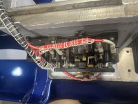
Next up was the main AC voltage in from the lathes main contactor panel. When I original ran the wire, I based it on the length of the original factory wire. In order to fit everything into one connection box, I replaced the factory vertical box, with a larger horizontal one. Thus created a problem, the AC main leads are too short!image.jpeg
So I ran 3 new leads from the main contactor panel.

In doing so, I spent some time looking at the panel and trying to better understand it.
image.jpeg
If I am correct in my thinking, there is a transformer for a light by the main switch on the front of the machine, a 208-220V coil... not total sure what its purpose is in starting the M/G. There is two heaters, both #1375. Before starting this project, I had no idea what heater's where in relation to a AC motor. Turns out they are a thermal overload safety device to protector the motor. Am I correct in thinking that these protect against long term over current situations, where as a fuse only protects against short circuits? Regardless, I need to figure out what the value of these heater units are. It is also worth noting that only leads T1 and T2 to the motor have heaters on them. T3 does not, so when I connect the lathe to the mains I will only be connecting it via L1 and L2 for this conversion and only T1 and T2 will be transferring power to the M/G unit.
 
Last edited:
I then connected the T1, T2, T3 leads and laced them. T3 is there incase I ever decide to convert back to the factory 3Phase system.
image.jpeg
Ok, we are finally starting to get somewhere, and then I ran out of the solder filled crimps I have been using, so there it sat for a few days while I waited for order from McMaster. This is when I also realized my location for the Supco really won't work here.
image.jpeg
Its going to have to lay horizontal on the bottom of the box to the left of the lower terminal block. That will give me more room for the wires.

When the rest of the crimps arrived from McMaster, I completed the connections for the Motor portion of the M/G.
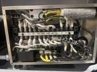
image.jpeg
I used this schematic to make the connections.
image.png
Ok finally, I am starting to get close to being able to power up and test the M/G to see if this will actually work!

But first time for some math.

The ampere reading on the input side (L1 & L2) of the H-A-S Static Converter will read as expected with any single phase equipment. That is, as the load increases, amperage will increase and both lines will be carrying the same amount of amperage. It is important to remember that these two lines will be carrying more amperage than the nameplate of a three phase motor will indicate. This is true because it will be carrying the same total power on two lines that it would be carrying on three lines when operating on three phase. The current required from single phase lines times 1.73 delivers the same power as three phase provided that the system efficiency and power factors are the same. For an H-A-S Static Converter-motor combination, the exact full load amperage taken from the single phase lines is calculated as follows:

(ConvertedMotorFLA=1.73PFH−A−S∗PF3Phase∗Eff3PhaseEffH−A−S∗FLA3Phase)

Where:

  • PFH−A−S= Power Factor of H-A-S Static Converter and motor combination
  • PF3Phase= Power Factor of H-A-S Static Converter and motor combination
  • Eff3Phase= Efficiency of three phase motor from nameplate or motor data
  • EffH−A−S= Efficiency of H-A-S Static Converter and motor combination
  • FLA3Phase= Three phase full load amps from motor nameplate
At full load conditions, it has been found that the power factor of the H-A-S Static Converter – motor combination is approximately .95 and its efficiency to be very nearly the same as when the motor is operated on three phase. The ratio of Eff3Phase/EffH-A-S then becomes unity and our equation simplifies as follows:

(ConvertedMotorFLA=1.73 /.95∗PF3Phase∗FLA3Phase=1.82∗PF3Phase∗FLA3Phase)

FLA3Phase for this motor is 13.2A

ConvertedMotorFLA=(1.73 /.95) x PF3Phase x 13.2

ConvertedMotorFLA= 1.82 x .95 x 13.2

ConvertedMotorFLA = 22.8 Amps!

The above relationship should be used to determine maximum L1 and L2 heater coil and fuse sizing.

At first thought, it would appear that this amperage is excessive; but it must be remembered that due to the winding connections, the I2R losses are spread out over all the motor windings.

Evidently, The T3 amperage may read higher than T1 amperage at no load or partial loads. This condition is normal and will not damage the motor or the converter. The T3 amperage will decrease as the load on the motor increases, while T1 and T2 amperages will increase as the motor approaches full load conditions. Although the actual amperages for L1 and L2 may be easily calculated as shown above, the amperage to use for the proper heater coil sizing for T3 is not so easily obtained. For practical purposes, however, the maximum T3 amperages should be calculated as follows:


T3 = .75 x FLA

So T3 = .75 x 22.8

t3 = 17.11


So based upon that info, I looked up the chart provided by Steelman and got the following:

Minium needed wire size for L1, L2, T1 is 10, for T2 it is 12 and for T3 it is 14. I used 10 for L1, L2 and T1 and then used 12 for T3.
So good to go there.

For the heater coil section the full load amperage is 22.8. I need to figure out what those Cutler Hammer #1375 heaters are actually rated at and confirm, they are adequate for this.

According to the Steelman chart, I should also add a heater to the T3 (starting circuit) with a value of 11.4 (thats a bit lower than the 17.11 I actually calculated) I will need to source one of these. I’ve never shopped for motor protection heaters before, so could really use some advice of what’s best to get for these. Seems like a big range on prices….

I'll need a 30 amp breaker for the mains.

The overall input wattage (I2R) of the motor at full load when operated with an H-A-S Static Converter does not exceed the overall input wattage of the motor when operated on three phase. For this reason, at full load conditions, the motor will have the same approximate temperature rise as if operated on three phase power.
 
Last edited:
While researching the heaters this AM, I found this post that contains the specs for the Cutler-Hammer heater coils:

"The table below is for use with 40C rise motors. Coils selected from this table will allow a maximum of approximately 125% of rated motor current. If protection is wanted at 140% of rated motor current use one size larger heater coil than as listed. To find the approximate tripping currents of the heaters, multiply the minimum currents by 1.25."

The relevant section for the 10EE would seem to be as follows:

"Motor Amperes - Heater Coil No.
9.96-11.0 - H1370
11.1-12.1 - H1371
12.2-13.4 - H1372
13.5-14.6 - H1373
14.7-15.8 - H1374
15.9-17.6 - H1375
17.7-19.0 - H1376
19.1-21.0 - H1377
21.1-22.7 - H1378
22.8-24.8 - H1379
24.9-26.7 - H1380

Below the table it reads "Each of these numbers, prefixed by 9586, is the catalog number of a package of two coils."

The "Size 1" CH contactor in the 10EE should be good for 27A continuous based on the information I dug up about NEMA size ratings." Ok thats good as It will now be seeing 22.8Amps so I will be well within its limits.

So bassed upon that chart the factory heater coils are good for 15.9-17.6 Amps. too low for the single phase conversion. I will need the 1378 or 1379 coils for T1 and T2. The original 1375 coil is adequate for the T3 section... I ended up finding all of these on E-bay for pretty reasonable prices, so ordered a replacement set of the factory 1375 ones, a set of 1378 and 1379. At $5 a coil, I figured its worth having them on hand. I think I will go with the 1378 series first as it will trip sooner than the 1379 to give the motor a little extra protection, if that doesn't work, ill go with the 1379 as the calculated amperage is right on the line for max load.

That same post brought up the question if just one leg would trip the overload, specially if wired for single phase:

"does anyone here know if these CH overloads will trip with just one "leg" or heater coil used, or if they require both to be in circuit, and as such wouldn't the current rating of the heater coils then be directly correlated to current flow across both "legs"? Obviously both would have to be wired for 3 phase configurations, but for anyone converting their machine to single-phase power and using the original contactor and overload combination, that could potentially present an issue whereby the original machine wiring in my machine as well as others as Cal has noted in other places on the forum has the contactor coil across L1 and L3, but the overload is on L1 and L2, so if one were to hook up to single phase with only one side of the overload in play, to avoid changing the way the contactor coil is powered, then only one side of the overload is wired up, and perhaps it wont trip at all, or will trip with different current characteristics than if both sides of it are wired up"

This is something I hadn't thought about, so I went out and took another look at my machine.
image.jpeg
Looking at my contactor, the coil is wired to L1 and the other side is connected to the right side of the overload switch (same side as T2 opposite of the main switch wire), so I believe the above concern isn't an issue as I am still using the coil as originally wired, and still using both heaters between leads T1 and T2. So Far so good (hopefully).

As wired via the schematic in my previous post the starter circuit is also connected to T1, so I'm thinking in this configuration, I may not need a separate heater for it, as it will be protected by T1's heater. However, this has potential to further increase the amperage on T1, but I think it will be ok, as the starting circuit should only have larger loads on it during starting, and then decreases as the motor load increases (opposite of T1's current draw) So as long as I am not starting the motor under a close to full load situation, that should be ok, in theory... or so I think.
Once the heater's I order arrived, I should be pretty close to being ready to power up for a test, to see if this conversion works.

However, something else I noticed looking at the contactor today, is one of the leads from the main forward / reverse switch on the head stock is connected to L3, which in this situation, I will not be using.
image.jpeg
I haven't had a close look at that switch, but from knowing that you can reverse the direction of any 3 phase motor by reversing any two leads, I'm guessing thats what thats doing. I'll need to have a closer look at this and figure out, how to change it if needed. First things first, get the M/G spinning before doing more mods than needed, and verify everything with a meter.
At least at this point, I feel like I'm starting to learn a few things about AC motors.... time will tell if I actually comprehend, what I think I am learning....the proof will be if it actually works.
 

Attachments

  • image.jpeg
    image.jpeg
    358.1 KB · Views: 1
No, they are not "common trip" as a multipole circuit breaker can be.

Yer good as you go.

Count on a decent UPSTREAM circuit-breaker, such as a Square-D "QO" (Quick Open, and they really ARE such, but right wise about it ....) to cover yerazz .... long before the stress reaches the point of hammering the thermal overloads.
Thanks Thermite. I am starting to think I could just run as is with one exception... I'll get to that in a minute, but in keeping with everything else on a 10EE best to keep with the bomb proof build spec.

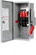
For the disconnect I ordered the following:

Siemens HF321N 30-Amp 3 Pole 240-volt 4 Wire Fused Heavy Duty Safety Switches. I found it for $55 in an amazon warehouse sale.

image.jpeg
I then ordered these fuses:

Bussmann BP/FRN-R-30 30 Amp Fusetron Dual Element Time-Delay Current Limiting Class RK5 Fuse, 250V Carded UL Listed

The Square D sub panel I installed in my garage previously is set up for 50 amp service. with dedicated circuits for the Bridgeport, my cabinet saw, welder, an accessory 110 circuit, and then finally a dedicated circuit for the lathe once I install it in its finally resting spot and run conduit and pull the cable for it. As long as I dont run any of the bigger draws simultaneously, shouldn't be an issue, and since its just me, I dont see that happening. The sub panel is nice, to, as its easy to lock all of the power out all of the machinery at once, so no worries about the 5 year old getting too curious if I'm not in the shop.

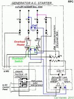
Back to the issue with the jumper form L3, I did a quick search, and found out that Cal has done a great job of documenting the mod needed here as it also applies when using a rotor phase converter.
Here are the two schematics he posted, showing that the jumper from L3 to #3 in the as built wiring needs to get changed to L2 to #3, with no further wiring mods needed.

image.jpeg
image.jpeg

In the previous two threads about converting the M/G unit to single phase, neither one of which fully documented the rest of the process, and at least for me, seemed to leave a bit of confusion about what exactly needs to happen with the rest of the wiring, and for sizing the heaters etc...partly due to the original links to the Steelman site no longer working. So hopefully I have now documented this process to make it easier for the next person to follow step by step.

FWIW, for the time I have spent thinking about and researching this and trying to make sense of it all, it would have been pretty easy to justify the cost of just buying a prebuilt phase converter. However I would have missed out on the learning experience this project has provided, so its been worth while imop.... now to do some testing once everything I ordered arrives.
 
I "began there" .. with used-but-like-new Canadian salvaged SQ D "600-Volt-class" (from NRi) but... the big and clumsy stuff was then repurposed to my MEP-803a gen set.

By separating protection (SQ-D "QO") from lock-out-able disconnect, I moved to "rotary" disconnects, pretty much for the whole shop.

Now.. the NEAT thing is the whole tribe use a 5 mm square non-metallic rod between knob and switchgear.

One CAN mount the whole shebang in a cast alloy "Bell Box" - common for outdoor outlets and lighting.

AND/OR the bezel can be flat on a NEMA box or even on the base casting of the machine-tool, whilst the guts - where the sparks reside - are at a some distance, inside, optionally also in a standard electrical box if not also within some other form of NEMA enclosure with "other stuff". Such as my DC Drives..

That remote 5mm square shaft.... only needs one small hole... so it enables flexibility, placement convenience, low profile... good looks... and is still "code" as well?

The first trio I found "New, In Box", 30A, 3-P, from a US maker, and for $25 each, yet!

What's not to like?
Now that the forum has moved out of the Dial up phase to the modern world of cheap broadband, any chance you could share a few pics. Would love to see your set up with how you incorporated the rotorary disconnects. Thanks.
 
"Vanilla" as it gets. I mean, if they are the same parts as any other mass-produced kit? Why would my knob & bezel look any different than any other rotary-disconnect?

:)

"In due course", I may post some of the WEIRDER stuff I have done, though.
Was hoping you did something creative with the mounts. Anyways, I always do best when contemplating ideas when I have a visual reference of the approach.
 
Ok, figured I'd keep going while waiting for the new heaters for the motor starter to arrive.

I changed the jumper wire in the starter for the F/R drive switch.
image.jpeg
Cal was kind enough to send me high-res of the as built and the modified starter circuits. I then drew up the wire schematics for the ASBUILT motor config and modified for Single phase, using the free online wire schematic drawer from Smartdraw.com. I added his files to it to have a copy of both versions.
image.jpeg
I sent this file out to get printed on metal in a standard 8x12 size... which perfectly matches the size I need for the front panel of the M/G junction box. This also makes it really easy to clearly see, exactly what wiring has been changed and how to easily switch back to the original.

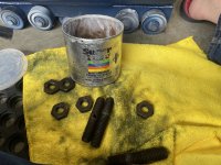
Next, its time to get the Exciter back in the lathe. It mounts using 3 bolts. The one in the front has a hole thought it, so you can use an alignment punch to adjust the belt tension. I gave these all a light coat of grease. I blued and oiled them with Boeshield T9 back when I tore the lathe down.
image.jpeg
The front bolt gets threaded into the Exciter, until l there is equal amounts of thread showing.
image.jpeg
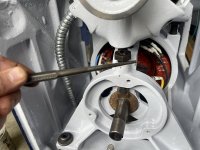
The exciter then gets lifted into the lathe, and rests on nuts on the back of the M/G's studs and then the front bolt gets screwed into the M/G using a tapper punch as a wrench.
image.jpeg
image.jpeg
I then installed the lower sheave. The belt that came on the Exciter had NAPA part 4L300W on it. So since I needed some DEF for the truck anyways, down to NAPA I went to get a belt.

Turns out, the belt is way too long!
image.jpeg
To get proper tension on it, I had to max out the front adjustment, and its not possible to raise the rear enough to get it in alignment. So this explains the severe wear on the belt when I purchased the machine.

A little research on PM and it looks like I need two 85A or 85A/P belts for the DC motor side of the machine... but I have not found any info for the Exciter side.
I found the Gates A85 Hi-Power II Belt, A Section, A85 Size, 1/2" Width, 5/16" Height, 87.0" Belt Outside Circumference for the drive side on Amazing for $24 a pop. Anyone have any idea what the correct belt is for the Exciter side?

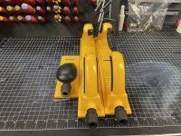
Time to switch gears for a bit. Last winter I saw a pretty good sale on MIRKA sanders and there mesh sanding supplies, so picked up two of their longer sanders, one flat and one where you can adjust the curved radius and a bunch of rolls of abrasive in each grit. I really wish I had this size when I prepped the base casting, but there is enough parts left on the lathe, that these larger ones will come in handy.
image.jpeg
The nice thing, is these are fully compatible with my Festool dust extractor. Before I left for work season last winter, I got the tail stock coated in bondo so time to get back to the body work. Hopefully by the time I have a batch of parts prepped for paint, we will actually get some dry weather.
image.jpeg
20 minutes of sanding later, and I got most of it flattened out.
image.jpeg
Notice the lack of significant dust. It sure is nice having good dust extraction! Anyways, more to come, but it's time for a beer.
 
Last edited:
Trading equities has the higher priority whilst the looter-idiots think theyselves "in charge".
The more greedy-foolish the "Government", the easier it is to generate wealth.
That’s exactly why soon as I am done with “work” season each year I bust my ass and take care of all of the yard work, house stuff and the years honeydo’s happy wife happy life then it’s back to doing the fun shit with out the boss nagging me.


Back
Top