What's new
What's new

G32 1" NPT Threading cycle

Rogue_Machinist

Hot Rolled
Joined
Jul 26, 2011
Location
Oregon, USA
Im looking for some guidance as to starting and ending points for the G32 tapered thread cycle. I get the U and W values need to be present for the taper. But I guess what im asking is what would be the starting and ending values and how do I calculate the X value for each cut. I cant cut these on the newer CNC with the G76 cycle already programmed into it as that machine is occupied with a hot large diameter job. Any input would be helpful.
 
The method is not very straightforward. It is like covering a distance of 100 km on a bicycle, for which a car would be more suitable.
You will need to command G32 multiple times, corresponding to each DOC. Since uniform DOC is not recommended, you will need to yourself decide and reduce the DOC for each subsequent pass. But, it can be done.

I am assuming that you know how to machine this thread using G76, but you need to machine it using G32.

On a piece of paper draw a slant line with the same NPT taper, representing the line passing through the thread root.
The horizontal projection of the line (say, L) will be the thread length, including Z clearance. The vertical projection of the line will be L/32 (Using this information, the line can be drawn without using angle measurements).
The specified target point (thread-end point) in G76 will be the coordinate of the left end of the drawn line.
Calculate the coordinate of the right end of the line, using geometry. (Z difference will be L, and X difference will be L/16, since diameter programming is being used).
This line corresponds to the last threading pass. The start point of G32 will be the coordinate of the right end of the line. The end point of G32 (i.e., its arguments) will be the coordinate of the left end of the line.
Now draw several lines of the same length which are parallel to this line and displaced vertically. Each line will represent intermediate threading passes. Choose the vertical displacements between the parallel lines in accordance with the desired DOC. The right end of each line will be the start point of the corresponding G32, and the left end will be its arguments. The vertical displacement between the first and the last line will be equal to the height of the thread (minus the first DOC).
After each threading pass, you will need to retract and bring the tool to the start point of the next pass.

If you need to machine too many pieces with different geometries, then writing a macro can be a good idea.
 
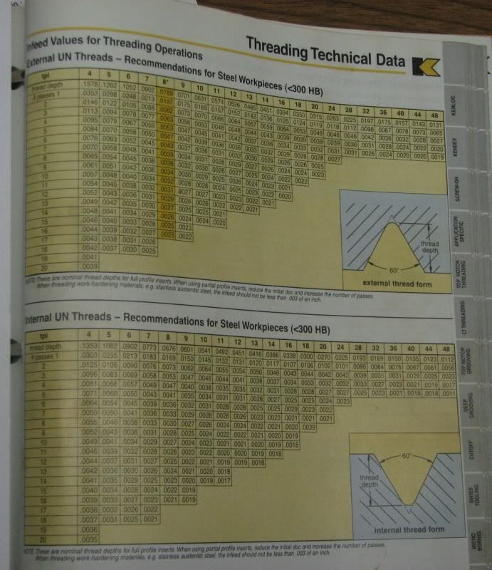
This chart can help you decide your X feeds:

KennaThreadingChartCat1010pg683.jpg


---------------

Think Snow Eh!
Ox
 
The method is not very straightforward. It is like covering a distance of 100 km on a bicycle, for which a car would be more suitable.
You will need to command G32 multiple times, corresponding to each DOC. Since uniform DOC is not recommended, you will need to yourself decide and reduce the DOC for each subsequent pass. But, it can be done.

I am assuming that you know how to machine this thread using G76, but you need to machine it using G32.

On a piece of paper draw a slant line with the same NPT taper, representing the line passing through the thread root.
The horizontal projection of the line (say, L) will be the thread length, including Z clearance. The vertical projection of the line will be L/32 (Using this information, the line can be drawn without using angle measurements).
The specified target point (thread-end point) in G76 will be the coordinate of the left end of the drawn line.
Calculate the coordinate of the right end of the line, using geometry. (Z difference will be L, and X difference will be L/16, since diameter programming is being used).
This line corresponds to the last threading pass. The start point of G32 will be the coordinate of the right end of the line. The end point of G32 (i.e., its arguments) will be the coordinate of the left end of the line.
Now draw several lines of the same length which are parallel to this line and displaced vertically. Each line will represent intermediate threading passes. Choose the vertical displacements between the parallel lines in accordance with the desired DOC. The right end of each line will be the start point of the corresponding G32, and the left end will be its arguments. The vertical displacement between the first and the last line will be equal to the height of the thread (minus the first DOC).
After each threading pass, you will need to retract and bring the tool to the start point of the next pass.

If you need to machine too many pieces with different geometries, then writing a macro can be a good idea.

I think I got it. Will be programming this in a few and posting what I get. These 1" npt will be for a customer order and they dont want parts that were put on the pipe threader. They want cut threads with definitive lead chamfer.
 
OX's picture of Kennametals book got me to thinking and so I went to their web site and found a program that they have that provides all types of threading program data. Naturally the selection of threading inserts are theirs, however it should work with similar inserts as well. Choose between inch and metric and then fill in the fields. Seems pretty straight forward and eliminates most all the math.

Here is the link: K Threading
 
Maybe it will help to recognize the diametral taper is 1/16" per inch. The Z destination- z start x .0625 equals the x diametral taper. With trig you can change the starting x and z point if you want to chase down the trailing flank. Or you can jump from side to side of the thread to spread the wear to both flanks of the insert.

Changing the z start point just changes the position of the tool along the thread flank.

This is a dumb cycle and you've got to tell it how to make each cut.


Back
Top