What's new
What's new

GD&T Angular tolerance question

Ecomm1

Plastic
Joined
Feb 7, 2023
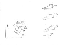
I have an angular check on a part that is hard to fixture. I am trying to see if it is possible to use trig to satisfy the Angular band on a part. ( Checking part with optical imaging that does not have Angular GD&T capabilities. ) Attached hand sketch is a simple illustration to see if my logic will satisfy the .010” Angular band tolerance.

Angle is 14 degrees, length of angle is .500”. Angular callout is .010”.


At 14 degrees, length of side opposite is .1209”.

If I add .005” to this, the Angle increases to 14.584 degrees.

If I subtract .005” from .1209” the angle decreases to 13.403 degrees.

Can I apply a tolerance of 14.00 degrees +.584/-.597 degrees and fall within the .010” angular bandwidth?


Thanks,

Ron
 

Attachments

  • Work1.jpg
    Work1.jpg
    215.2 KB · Views: 32
You can theoretically do this. If your part thin it's a reasonable thing to do, if thick not so reasonable. But it's better to put the part on a sine plate and measure the .010 directly.
 
Hi Ecomm!:
My understanding is that technically, you cannot, and I say so because the tolerance band is parallel to the angled surface so anything within that band is a "good" part.
If you express the tolerance as an angular one, the tolerance band is no longer parallel but is wedge shaped, so a "good" part is no longer quite the same as a GD&T "good" part.

Having said that, you can make a case that in the practical world if the angled surface is actually fairly flat, you can get pretty close with your strategy and you will not accept "bad" parts, but if my thinking is correct, you may reject some "good" parts.

Cheers

Marcus
www.implant-mechanix.com
www.vancouverwireedm.com
 
I agree with what Marcus says.

You may still be able to check the tolerance band optically if you set up a .010 wide band on 14* and confirm the entire surface falls within this band. It's seems easier than checking the angle.

It's still probably harder than a sine plate but maybe you are thinking this way so you can streamline your whole part inspection.
 
Thanks for the good advice. Always nice to be able to exchange ideas on a forum like this without all the social media shenanigans!

Ron
 
It would be better to see he print. Lets say you have an Optical comparator. So, you define the X and Y from the datums. You could ZERO in on one of the 'corners' or intersections of the angle. Then trig out various check points along the angle. Or set the XY to nominal. Then raise 1/2 the tolerance up and down, with the cross hair at the nominal angle.


Back
Top