What's new
What's new

Gear tooth question & the "Yugo" od surface grinders

Joe Michaels

Diamond
Joined
Apr 3, 2004
Location
Shandaken, NY, USA
Last winter, I swapped my Sanford surface grinder for a Boyar Schultz 612 Challenger surface grinder. The reasons for this was to get increased capacity. The Boyar Schultz grinder had an unknown and checkered past from all indications. Due to health issues, I was unable to get around to working on this grinder until recently. Overall the grinder seemed like a tight machine, with a few issues. As I cleaned up and put things to rights on this grinder, I realized a Boyar Schultz surface grinder is the equivalent of a "Yugo" when compared to the likes of Brown & Sharpe, Reid, and others. For my purposes, it will be a fine grinder.

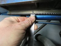
The issue which as proved to be something of a conundrum for me is the pinion for the table feed. This pinion is a spur gear, engaging a rack on the underside of the table. Apparently, a previous owner had the machine apart and had lost the original pinion. He then put in an 'off the shelf' pinion, but the result was a 'notchiness' as the pinion engaged the rack.

I took this pinion off and determined it to be a 16 pitch x 18 tooth gear. That was the easy part. I then started to measure the pinion teeth using my gear tooth vernier. The thickness across the pitch point and tooth depth all coincide with both 14 1/2 degree & 20 degree pressure angle gear teeth. I bought a 20 degree PA x 16 tooth pinion on eBay and it was exact in overall dimensions (width, hub diameter & bore) to what was on the grinder. The result was the same 'notchiness' and rough movement of the table. It took some effort on the handwheel to crank the table thru its travel, rather than having it gliding smoothly.

I had found the original electro-mechanical lubricator was incomplete when I got the grinder. I fitted a used Bijur electro mechanical lubricator to the grinder, and changed the drive motor to increase the frequency of 'shots' of way lube. I first ran some "Marvel Mystery Oil" thru the lubrication system and broke lines at various fittings to be sure the lubrication lines were cleared and had good flow. In taking things apart to check lubrication lines and do some cleaning, I did notice the scraping on most of the sliding surfaces was still pretty much all there. With the lubrication issue resolved, I turned back to the table feed pinion.

OK, sez I, let's see where the teeth are hitting hard when they engage the rack. Having two identical pinions, I could sacrifice one to trying to get a better running rack & pinion set. The rack teeth look to be 'stub' teeth. I first determined the pinion was a little on the large side for outer diameter, so set it up in the lathe and skimmed about 0.015" (total) off the OD. No improvement in how things ran. I then figured that with a skim cut on the OD, the corners of the teeth were likely too sharp. I used my die filer to put a small radius on the tips of each tooth where the flanks met the crests. Again, no improvement.

I then figured to open up the running clearance, so using the die filer, skimmed a bit off the flanks of each tooth, working the gear in a curve to try to maintain the involute profile (fat chance of that). The result is the notchiness has turned into more of a rumbling with some slight vibration when the table is moved.

The question in my mind is whether I need to cut a 14 1/2 degree PA x 16 pitch x 18 tooth pinion with full-profile teeth, using the appropriate gear cutter, or, should I use a 16 pitch cutter made for cutting 135- rack teeth ? I ran gear tooth math using my 'Machinery's Handbook", with the voices of my machine design teacher and advanced machine shop teacher back at Brooklyn Technical HS running thru my mind. I've done very little actual gear design over the course of my career, but a simple spur gear pinion should not be such a conundrum. I am guessing the last guy grabbed a 20 degree PA pinion and since it fit in terms of number of teeth and overall dimensions, ran with it. My other guess is, by process of elimination, a 14 1/2 degree PA pinion is what's needed. I figure I may as well cut my own pinion so I can play around with OD & tooth depth. I also figure that, instead of steel (as the pinions I do have are), I will make the new one out of bronze.

I would appreciate some help in determining which number cutter to get. The obvious choice is the cutter number 6 ( 17-20 teeth), but the fact this pinion engages a rack with what appear to be stub teeth has me wondering whether a number 1 cutter ( 135 teeth-rack) should be used. It's a question I never had to deal with in the 56 years since I first cracked the "Machinery's Handbook" snd over the ensuing years of my career and 'retirement'. I appreciate the considered wisdom of everyone here, and wish everyone the best for this Holiday Season.
 
I wouldn't put down your model of grinder, they were/are popular, so you will see many of them, some in bad shape, nature of the market.
 
Might be worth while to acquire a 1.5 Metric Module pinion

16 DP is 1.588 Metric Module - which has slightly "fatter" teeth

The 1.5 Module will also be ever so slightly smaller in pitch diameter
 
I have a Boyar Schultz 6 x 18 hydraulic that looks quite similar to a 6-x 12 but with a longer travel .
I don't know for sure if they use common parts or not so I don't know if this will be of any help.
The rack on mine appears to have 16DP 14-1/2 degree teeth .
with the overall rack thickness of .489" by a quick check with my low priced caliper .
I can't see the pinion with out taking the table off but mine is fairly smooth in spite of having about 1/2" of backlash at the handle when I reverse the travel .
My rack and pinion may have some wear from before I got it some 30 years ago but I take advantage of the hydraulic when ever I can so it doesn't bother me to often .
Jim
 

Attachments

  • IMG_1604.jpg
    IMG_1604.jpg
    81.4 KB · Views: 71
  • IMG_1606.jpg
    IMG_1606.jpg
    83.3 KB · Views: 63
  • IMG_1607.jpg
    IMG_1607.jpg
    81.6 KB · Views: 62
  • IMG_1608.jpg
    IMG_1608.jpg
    88 KB · Views: 63
  • IMG_1609.jpg
    IMG_1609.jpg
    87.4 KB · Views: 59
Thank you to John Oder & Jim Christie for helping me solve the gear riddle. The fact that Jim's template gauge confirms 14 1/2 degree 16 pitch will likely solve the riddle. I believe the last guy to work on this grinder had used a 20 degree PA 16 pitch pinion. I was only able to find another 20 degree PA 16 pitch pinion on eBay and got the same running as with the pinion that was on the grinder when I got it. This leaves me with two possible thoughts:

MSC has a 16 pitch 14 1/2 degree PA 18 tooth pinion, made of steel, correct bore for about 30 bucks;

or-

Invest in a milling cutter and cut my own pinion out of bronze and have the added ability to play with some of the dimensions

I do have some pieces of "Micarta" (canvas reinforced phenolic) about 2" thick, so could make a new pinion out of that material. That material was commonly used for 'silent running' gears, and for some automotive timing gears.

I'm leaning towards buying the milling cutter, though an off-the-shelf pinion gear would be a whole lot quicker.

Thanks again-

Joe Michaels
 
Some times Martin Sprocket or Boston Gear have stock on small pinions like that and the last ones I bought through one of their distributors was not as expensive as I might have thought some where in the $20.00 to $ 30.00 range too but it was a while ago .
I see Boston has some in Bronze too but they may be a bit narrow.
https://www.bostongear.com/-/media/.../p-1930-bg-sections/p-1930-bg_spur-gears.ashx
I didn't check Martin.
Power Transmission, Material Handling & Hand Tool Manufacturer
I have a length of Boston's Bronze Pinion Wire that I will check for size later but I think the pitch may be too fine .
Jim

P.S. I checked and my pinion wire is unfortunately 24DP
 
I'm leaning towards buying the milling cutter, though an off-the-shelf pinion gear would be a whole lot quicker.
If you get the cutter, get it for the part you are making (#6 ?) rather than the mating part (#1).

If you are going to mess with proportions, I'd make the addendum as long as possible, to give you a little more teeth in contact and the transition from tooth to tooth smoother. But that's not going to be much, so you're just doing it for your own satisfaction.

Want to go crazy ? Make a new rack too. Helical. That'll be smooth :D
 
(snippage)

The result was the same 'notchiness' and rough movement of the table. It took some effort on the handwheel to crank the table thru its travel, rather than having it gliding smoothly.

(more snippage)

I first determined the pinion was a little on the large side for outer diameter, so set it up in the lathe and skimmed about 0.015" (total) off the OD. No improvement in how things ran. I then figured that with a skim cut on the OD, the corners of the teeth were likely too sharp. I used my die filer to put a small radius on the tips of each tooth where the flanks met the crests. Again, no improvement.

(yet more snippage)

The result is the notchiness has turned into more of a rumbling with some slight vibration when the table is moved.


All of this is very commonly the characteristic function of what one gets with milled tooth spaces using cutters unsuited to doing one thing well. The cutter for 18T covers tooth counts ranging from 17T - 20T and is an approximation. Put simply - it does none of them well, nor correctly. Those cutters are fantastic for making a gear without expensive machinery, tooling, or training. What they do not do is make a correct Involute. As long as one understands and accepts that, all is well. But one does have to live with the lumpiness ( or "notchiness" ) of the result. It is the reason that such gears are never to be used within high speed gear trains. ( there is no true rolling/constant velocity to their use )

If you just have to have a smooth, rolling engagement, ( and a surface grinder certainly qualifies, here ) then I would suggest obtaining a properly generated Pinion and installing it.

Just understand that space milled gear is never going to be ideal. They're great for price point and/or "just make it go 'roundy 'round" ). And that's about all.

Take this as worth just barely less than you have paid for it.

ZK - resident GearSnob
 
If you get the cutter, get it for the part you are making (#6 ?) rather than the mating part (#1).

If you are going to mess with proportions, I'd make the addendum as long as possible, to give you a little more teeth in contact and the transition from tooth to tooth smoother. But that's not going to be much, so you're just doing it for your own satisfaction.

Want to go crazy ? Make a new rack too. Helical. That'll be smooth :D

If it were me ( and doing it for my own staisfaction ), I'd use an AntiBacklash Spur Pinion. Simple and easy; Done. :cool:
 
IIRC one brand of grinder uses a flexible steel cable to move the table.
Could you use a bicycle chain & sprocket ?
 
ZK is someone here I trust on gears, b ut since my thoughts do not directly contradict what he said, i will offer them.

Should be possible to easily measure depth of teeth on rack and be certain if it is a stub-tooth or standard?. If stub, should not the mating pinion be stub-tooth as well? I do not think a standard gear-cutter, even for the correct # of teeth, can cut a stub tooth-space.

Rack, as gbent said, should be easy to measure to be sure of PA.

You could try a stock pinion of correct count, pitch, and PA, and if still bumpy, you could try lapping the pinion and rack together. But depending on exactly what profile defect mismatch is causing the bumpiness, lapping could make it worse. Then your rack would be bad, too.
Another suggestion, a new piece of standard stock rack, with a new matching pinion. But hard to say if you would get a pinion with properly generated teeth, as per ZK's observation. I do not know how beefy your parts are, but automotive steering-gear racks are smooth and helical..maybe not long enough.

Next-to- last and least practical but perhaps most interesting suggestion, make a hob (acme-ish screw, gashed, hardened) to match rack profile, and buy that hobber.

Last thought for now. I think you could graphically generate the correct involute profile for the needed tooth-space, taking into account PA, pitch, stubbiness, etc.. Might need a pantograph to draw it big enough to get right and then reduce it to actual size. Grind a fly-cutter (might need optical comparator to get that close enough) and mill your new pinion with your milling machine and dividing head.

Not last. Might the bumpiness be reduced if you sawed the rack in two, lengthwise, then sawed the pinion in half to make two with half face-width, then offset both by 1/2 tooth?
 
Thanks to everyone who has offered their advice about the pinion and 'lumpiness' on the table feed on my Boyar-Schultz surface grinder. For the near term, I ordered a 14 1/2 degree PA, 16 pitch, 18 tooth pinion from MSC. Not sure who made it, whether Chinese, Boston Gear, Martin, or ? The main thing is that this will be a 'factory made' pinion, probably made on something a lot more accurate than my cutting a pinion with a dividing head and involute cutter.

Diggerdoug: I do recall one manufacturer of surface grinders using a piece of small diameter cable (aircraft control cable comes to mind) and a winding drum to move the table. It was the same setup as the steering on smaller boats, with the wire rope wound lefty-righty on the drum. It would certainly be a smooth system, and with the wire rope tensioned with a turnbuckle or similar, it would be a zero backlash system.

Another idea I had was to use 'timing belt' material and a timing pulley to move the table. With a spring loaded idler pulley to maintain tension on the timing belt, this would provide a zero backlash table feed.

However, since this is a well-used hand feed surface grinder with no money invested in it, I will stick with the rack and pinion for now. It's amazing how something so basic as a spur gear pinion and rack can be such a conundrum. However, gearing and gear design is a science unto itself in my book. I remember at Brooklyn Technical HS in the mid 60's, how we kids were given gear design problems. I do not recall ever having to design a rack and pinion, just sets of spur gears. The teacher would start off with something like: "-- Horsepower at --- rpm is transmitted between two parallel shafts --- inches on centers. The input shaft turns at --- rpm and the output shaft is required to turn at ---- rpm. Design a set of spur gears, 14 1/2 degree pressure angle (we NEVER design 20 degree PA gearing for some unknown reason), steel pinion, gray cast iron bull gear..." We'd open our "Machinery's Handbooks" and get busy crunching numbers, using slide rules for some portions of the calculations and longhand multiplication and division for the final set of gear data numbers. We'd submit the 'table of gear data', done on a 'board and tee square' with 'lettering and linework conforming to the standards for Mechanical Drawing at Brooklyn Technical HS'. We'd get the 'tables of gear data' back with corrections and a grade, which included grading on neatness, lettering and linework. Next came making a pencil drawing of the gears, usually with the bull gear shown as half a gear, table of gear data shown on the drawing, and a section thru the bull gear to show the hub, rim and spoke design.

Therein lies a funny story that, today, would be considered about as 'politicially incorrect' as it gets. Our teacher had emigrated to the USA from Ireland, sometime in the 20's. He was educated by Jesuits, and was a Licensed Professional Engineer in NY State. During the Depression, he became a teacher at Brooklyn Technical HS and never returned to working as an engineer. He'd found his true calling in educating future engineers, machinists and similar. Our teacher had a 'foine Irish Brogue' and was a hard taskmaster. I spent some hours in class and at home drawing a set of spur gears, with the bull gear shown as a 'half gear'. I thought I had made a good drawing. Our teacher, returning the corrected graded drawings, called me to the front of the class room. It went something like: "Michaels, me lad, tell me now... where are we located on this God's Earth ?" "Brooklyn, NY, sir." "Well then lad, what country would Brooklyn be in ?" "The United States of America, sir". "Lad, what is the language of the land here ?" "English, sir" "That is correct, lad. Now, how is English written ?" "With letters, sir." "And lad, would you be telling us how those letters are run, left to right, right to left, or top to bottom vertically ?" "Left to right, sir". With that, the teacher unloaded with both guns, having held himself in check to deliver what amounted to a set of combination punches. "Lad, you've told us we are in the USA, English is the language of the land, and is written left to right. That being the case, could you please tell us why in the bloody hell you dimensioned your drawing from right to left ? We are in Brooklyn, not Jerusalem, and your drawing is not 'the Daily Forward' (the leading Yiddish newspaper in NYC), though I suspect your people read that socialist rag, "Der Freiheit" ('the Freedom', a Socialist Jewish newspaper written in Yiddish)." I stood there, taking all that our teacher had to say and hearing the class around me roaring with laughter along with the teacher. He then took my drawing and ripped it in two, in front of the class. He told me he was not entirely hard-hearted, and I'd be able to re-submit the drawing, dimensioned left to right, 'for a lesser grade, but a grade nonetheless'.

I re-drew that set of spur gears, got a good grade on it, and then traced the drawing in 'India Ink' as the final step. Despite the carryings-on of that teacher, I did well with him and he gave me very high grades. I emerged none the worse for the experience, and a good deal for the better. This whole exercise with the pinion on my surface grinder has me reliving those days at Brooklyn Technical HS, remembering and glad I got the education I did. Funny to recall that teacher with his brogue, rattling off gear terms and riding us kids hard. I did well in my grades and enjoyed the education. When I graduated, I remember introducing my parents to that teacher and he was pleased to meet them and had good things to tell them. I'm sure he is passed to the great beyond, but I'm also sure he is chuckling and remarking about this whole matter in that brogue of his.
 
IIRC one brand of grinder uses a flexible steel cable to move the table.
Could you use a bicycle chain & sprocket ?
Chain drive is really lumpy. Think of a sprocket - it's not a circle, it's a polygon. And the chain is straight links. So as the chain rotates onto and off of the sprocket, it's moving in series of jerks. That's one reason they came up with silent chain, and why most cars use timing belts now.

I know that Brown & Sharpe made a 6 x 12 (?) surface grinder that used a strap wrapped around a cylinder to move the table. Had a big lever on the front that you'd swing, rather than a circular handle.

In Joe's case tho, easiest is to just use the right pinion :)

And in response to zahn, space cutters aren't THAT bad for a job like this ! The reason they are not so perfect as involutes is they aren't involutes. They are made to another system called "composite" ...
 
I wouldn't put down your model of grinder, they were/are popular, so you will see many of them, some in bad shape, nature of the market.

They are/were VERY popular for applications requiring a lot of angular and radii wheel dressing.
Makers of form tools, and misc mold and die work are great examples.

Plain surface grinding is not quite up to a REID, for example.

But they were cheaper and handier.

Kind of like comparing a Bridgeport to a Milwaukee.


Back
Top