Vernon Tuck
Stainless
- Joined
- Oct 26, 2008
- Location
- Brenham, Texas
Howdy folks,
Some time ago I acquired a 1962 1-22 Tracemaster mill with a B360 3D True-Trace unit, in unknown working condition.
According to the successor corporation that owns the rights to True-Trace, the tracer valve is totally obsolete and no parts are available.
Based on a read of some old historic brochures, when Gorton came out with their Mastermil line, now fitted with the True-Trace units, they pitched the "Tracemasters" as being "fully functional manual mills". No doubt this approach was intended to appeal to and placate the "old school" shop owners who weren't so sure about stepping up to "new technology" and wanted to keep one foot in what they knew and understood.
I took solace in this "fact" because I always had doubts about whether the tracer unit would work. Hence, it was comforting to know that I could use the machine as a manual mill if it did not.
Because the machine was so grungy, and because my attention is so divided with so many other grungy acquisitions, I never fiddled with the knobs and levers until I could get around to thoroughly cleaning and servicing the machine. Only yesterday, we finally got around to it. For no particular reason, I started with the Y axis, cleaning the ways on both sides of the saddle with mineral spirits, then applying fresh oil, and moving the saddle back and forth until it was clean and lubed. Then I cleaned and lubed the vertical ways and got the knee clean and operating smoothly through its full range of travel. Both the saddle and the knee have conventional acme lead screws to mechanically control their full range of travel. The knee is also controllable by a hydraulic cylinder.
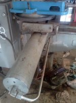
Finally, I turned my attention to the table. The left end of the table is fitted with a long hydraulic cylinder. The table does have a hand wheel at the right end but has no visible lead screw. The actuator shaft is smooth (ball screws???). After cleaning and lubricating the table, and greasing the hand wheel, I discovered that, stop to stop, the table's total mechanical range via the hand wheel, is only about FIVE INCHES!
It happens that this machine was custom built in 1962 for the Marshall Manned Space Flight Center, the predecessor to NASA. Hence, I've now been b**** slapped by the possibility that it indeed was NOT built as a "fully functional manual mill".
If this turns out to be the case the burning question becomes:
Where to now???
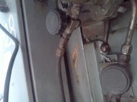
My dilemma with the tracer unit is that it may or may not work. The problem is that facing spending hundreds of dollars in new hoses and fresh fluid just to test the system. Even if it works, there are no guarantees from one day to the next. So, it's possible, perhaps even likely, that, only after I spend a significant amount of money, the tracer won't work at all, or will work for only a short time before giving up the ghost.
I may be a crazy fool, but that doesn't mean I'm stupid... so, I may indeed take the plunge. Nevertheless, before I do, metinks it is prudent for me to explore the full range of options.
Although I'm no expert, to my eye, this mill is in very good shape, all things considered. Also, I'm a simpleton. And this mill is.. er.. simple. The table itself, is quite large and wide. It has a fixed head that neither swivels nor tilts. The motion is controlled by a long hydraulic cylinder that sticks out the back of the ram. So, with an operational tracer and/or viable alternative means of mechanical and/or hydraulic control, the work envelope is quite spacious.
Save for those add-ons, the mill is totally manual. It doesn't have the "dyna drive", power down feed, or any of those other accessories that are so often on these mills and that, today, don't work, due to the obsolete vacuum tube electronics. Save for the hydraulics, the mill is fully functional and seems to be tight and well cared for.
In summary:
On the Y axis
the table's range of mechanical movement is quite spacious. This could be increased dramatically by the ram, which is only hydraulically controlled as best I can tell.
On the Z axis
there is full mechanical control of the knee with a conventional crank. The knee is also controllable by a hydraulic cylinder.
The spindle has a down feed is fully mechanical and fully manual. There is a lever (like a drill press) or a micrometer stop controlled hand wheel. Otherwise, the machine has no power down feed, no table power feed, and no knee power feed.
Hence, on Y and Z, I'm golden.
But on X, unless I'm overlooking something obvious, from stop to stop, I am limited to a puny 5 inches of travel, more or less.
A friend, and member here, (you know who you are...) has suggested that fitting a 48" Bridgeport lead screw and half nut might be an option. It appears that a brand new lead screw can be had on ebay for under $400. Under that scenario, I would endeavor to retrofit a lead screw and install a DRO, and scrap the hydraulics. As a practical matter this is appealing. However, the machine DOES have some historic value in my mind. And by that, I'm not thinking "I can sell it for a bunch of money". Rather, I say it from the stand point of "responsible conservatorship". I only care about money when I'm totally out of it.
So, under that mind set, I'm wondering about the viability of finding parts from another appropriate Gorton mill, and re-fitting it with such components as may be required to make it a "fully functional manual mill".
The ideal solution from my standpoint would be an approach that would not permanently alter the mill, in case the Smithsonian comes knocking at my door after I'm dead and gone. I've thought about how I might install a DRO and even power the cylinder with a hydraulic hand pump such as a porta-power unit, or some similar off the wall fix that will overcome the problem cheaply, and without permanently altering the machine.
If y'all have any suggestions as to a viable retrofit I will be happy to hear them. I have not given up on the idea of getting the hydraulics going. However, I'm actually considering buying a hydraulic hose crimper and doing it myself rather than plunking down the kind of money it would cost to replace all the lines on the mill.
But any and all ideas, observations, and comments will be welcome - especially those by somebody who's "been there and done that".
Sincerely,
Vernon
Some time ago I acquired a 1962 1-22 Tracemaster mill with a B360 3D True-Trace unit, in unknown working condition.
According to the successor corporation that owns the rights to True-Trace, the tracer valve is totally obsolete and no parts are available.
Based on a read of some old historic brochures, when Gorton came out with their Mastermil line, now fitted with the True-Trace units, they pitched the "Tracemasters" as being "fully functional manual mills". No doubt this approach was intended to appeal to and placate the "old school" shop owners who weren't so sure about stepping up to "new technology" and wanted to keep one foot in what they knew and understood.
I took solace in this "fact" because I always had doubts about whether the tracer unit would work. Hence, it was comforting to know that I could use the machine as a manual mill if it did not.
Because the machine was so grungy, and because my attention is so divided with so many other grungy acquisitions, I never fiddled with the knobs and levers until I could get around to thoroughly cleaning and servicing the machine. Only yesterday, we finally got around to it. For no particular reason, I started with the Y axis, cleaning the ways on both sides of the saddle with mineral spirits, then applying fresh oil, and moving the saddle back and forth until it was clean and lubed. Then I cleaned and lubed the vertical ways and got the knee clean and operating smoothly through its full range of travel. Both the saddle and the knee have conventional acme lead screws to mechanically control their full range of travel. The knee is also controllable by a hydraulic cylinder.
Finally, I turned my attention to the table. The left end of the table is fitted with a long hydraulic cylinder. The table does have a hand wheel at the right end but has no visible lead screw. The actuator shaft is smooth (ball screws???). After cleaning and lubricating the table, and greasing the hand wheel, I discovered that, stop to stop, the table's total mechanical range via the hand wheel, is only about FIVE INCHES!
It happens that this machine was custom built in 1962 for the Marshall Manned Space Flight Center, the predecessor to NASA. Hence, I've now been b**** slapped by the possibility that it indeed was NOT built as a "fully functional manual mill".
If this turns out to be the case the burning question becomes:
Where to now???
My dilemma with the tracer unit is that it may or may not work. The problem is that facing spending hundreds of dollars in new hoses and fresh fluid just to test the system. Even if it works, there are no guarantees from one day to the next. So, it's possible, perhaps even likely, that, only after I spend a significant amount of money, the tracer won't work at all, or will work for only a short time before giving up the ghost.
I may be a crazy fool, but that doesn't mean I'm stupid... so, I may indeed take the plunge. Nevertheless, before I do, metinks it is prudent for me to explore the full range of options.
Although I'm no expert, to my eye, this mill is in very good shape, all things considered. Also, I'm a simpleton. And this mill is.. er.. simple. The table itself, is quite large and wide. It has a fixed head that neither swivels nor tilts. The motion is controlled by a long hydraulic cylinder that sticks out the back of the ram. So, with an operational tracer and/or viable alternative means of mechanical and/or hydraulic control, the work envelope is quite spacious.
Save for those add-ons, the mill is totally manual. It doesn't have the "dyna drive", power down feed, or any of those other accessories that are so often on these mills and that, today, don't work, due to the obsolete vacuum tube electronics. Save for the hydraulics, the mill is fully functional and seems to be tight and well cared for.
In summary:
On the Y axis
the table's range of mechanical movement is quite spacious. This could be increased dramatically by the ram, which is only hydraulically controlled as best I can tell.
On the Z axis
there is full mechanical control of the knee with a conventional crank. The knee is also controllable by a hydraulic cylinder.
The spindle has a down feed is fully mechanical and fully manual. There is a lever (like a drill press) or a micrometer stop controlled hand wheel. Otherwise, the machine has no power down feed, no table power feed, and no knee power feed.
Hence, on Y and Z, I'm golden.
But on X, unless I'm overlooking something obvious, from stop to stop, I am limited to a puny 5 inches of travel, more or less.
A friend, and member here, (you know who you are...) has suggested that fitting a 48" Bridgeport lead screw and half nut might be an option. It appears that a brand new lead screw can be had on ebay for under $400. Under that scenario, I would endeavor to retrofit a lead screw and install a DRO, and scrap the hydraulics. As a practical matter this is appealing. However, the machine DOES have some historic value in my mind. And by that, I'm not thinking "I can sell it for a bunch of money". Rather, I say it from the stand point of "responsible conservatorship". I only care about money when I'm totally out of it.
So, under that mind set, I'm wondering about the viability of finding parts from another appropriate Gorton mill, and re-fitting it with such components as may be required to make it a "fully functional manual mill".
The ideal solution from my standpoint would be an approach that would not permanently alter the mill, in case the Smithsonian comes knocking at my door after I'm dead and gone. I've thought about how I might install a DRO and even power the cylinder with a hydraulic hand pump such as a porta-power unit, or some similar off the wall fix that will overcome the problem cheaply, and without permanently altering the machine.
If y'all have any suggestions as to a viable retrofit I will be happy to hear them. I have not given up on the idea of getting the hydraulics going. However, I'm actually considering buying a hydraulic hose crimper and doing it myself rather than plunking down the kind of money it would cost to replace all the lines on the mill.
But any and all ideas, observations, and comments will be welcome - especially those by somebody who's "been there and done that".
Sincerely,
Vernon
")