What's new
What's new

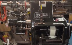
Gorton 375-2 Tool Cutter Grinder

Back in post #15 I discussed belt and pulley sizes, and speeds. Moving on to do something about it.

Most 4" wheels are most efficient in the 5200 rpm range. The way this machine was set up as I got it, was 3200 rpm with a 6" wheel. For now my goal is to move back to the machine's more natural 4" wheels. I have acquired multiple different wheels and cutters. Most are rated at 5000rpm or higher. But I have one rated 4800 rpm, and a cutter a 4500 rpm, as I recall.

Eric had a good suggestion of using a 3 phase motor with a vfd so I could set speeds where ever I want. I also prefer 3 phase motors. But due to limited floor space, I will need to roll this machine into and out of my way. So I'm thinking a single phase cord will be easier to drag around. Plus I'm not quite as experienced as regular grinder guys to know the fine details of finishes with higher and lower speeds.

Somewhere I saw Buck mention multiple pulleys for speed changes. I think this may work for me. For now I plan on running the machine at 4500 rpm spindle speed until I'm comfortable. But I also have a 2nd spindle pulley to take me to 5050 rpm, should I decide to get more fancy.:D

My motor speed should be 1725. I'm using 3L belts. The pulleys available are deeper groove for 3L and 4L use. Using 3L belts will put my motor pulley at 5.86" OD:

169.JPG

To get the 4500 rpm at spindle, I'm using a 2.25" OD for 3L pulley at spindle:

170.JPG

With those pulley OD's and motor speed at 1725 rpm, we can see my spindle speed should be 4500 rpm using the calculator:

171.JPG

That calculator is here:
 
Last edited:
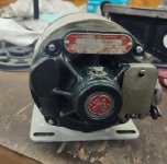
Upon receiving the pulleys, I found the motor pulley more than 3lb. The motor in the machine only had a 1/2" shaft, plus the end bearings look like very light duty. So I started shopping around. I found a vintage GE motor that has a 5/8" shaft. Not ball bearing ends, but has bushings that takes gits oils for the end bushings.

Considering this machine is from between 1943 & 1953, I thought this motor would be a nice addition. Its a 1/3hp, where the original would have been 1/4 hp. Here's a pic of the new motor and its new pulley:

172.JPG 173.JPG

I stuck a multi meter on the motor to make sure it wasn't shorted out, then put power to it. It works.

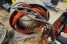
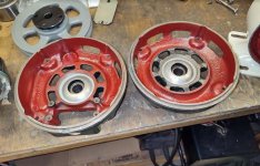
Feeling I have something I can use, I took it apart to get it cleaned up. Glad I did:

174.JPG 175.JPG 176.JPG

I'll be working to get this cleaned up and ready to rock.
 
Working to get the motor cleaned up:

177.JPG

On the windings, I first used very light air pressure to blow the loose dirt off. I then used clean mineral spirits and gently washed with a paint brush. Using low air pressure again, I blew it mostly dry, but let it sit in the sun for about 30 minutes to let residual spirits dry. At that point I used electrical contact cleaner to thoroughly wash it down, at let it dry out again.

178.JPG 179.JPG

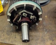
Took apart the end of the rotor and got it cleaned up too.

180.JPG
 
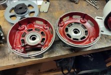
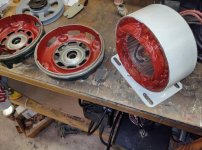
Getting the motor painted. I used Glyptal 1201 Red enamel, which is an insulating paint that was developed by GE, for the windings and inside the end bells. The first 3 pics are without a camera flash:

181.JPG 183.JPG 182.JPG

The next two are with a camera flash:

184.JPG 185.JPG
 
I got the motor installed, and it was a perfect match to the original mounting. In fact, this motor is more correctly aligned than the one I took out, It must have been replaced, and the mounting base had been modified, so it wasn't quite right. Good news, this one is just right.

193.JPG 194.JPG

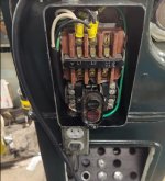
I re-wired everything, motor to starter, the 110v outlet, and a new power cord and plug. Cleaned up the starter:

195.JPG

I got the start cover dressed up a bit:

197.JPG

With power connected, the light does its job well. No belt or pulleys on yet, but starting the motor, its dead silent. Real nice:

196.JPG

The last items left are the belts and pulleys. Hope to have that finished during the week.
 
Got around to getting the pulleys on with a 3L belt:

200.JPG 201.JPG

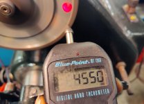
Double checking the spindle speed with a photo tach, its coming in right about where I wanted it at 4550 rpm:

202.JPG

The spindle shaft is 7/16" in OD. All the wheels I picked up have a 1.25" ID hole. I'm going to make up some bushings for those.
 
I am curious where you are finding your grinding wheels. I bought a Gorton 375-4 grinder last year and I am having a hard time finding grinding wheels with a 3/8" back. Normal wheels now have 1/2" backs to them. Are you just using the current 4" wheels with 1/2" backs on them?
 
Wow, nice job Texas.
A double pully for 3500 and 6500 RPM is suitable/OK for aluminum oxide and diamond wheels. The mounting flange/adaptor should be for a common wheel blotter so no matter the shaft size one can go up the 1 1/4". The adapter back wall should be 3/8+ so able to withstand tightening with not distorting. the direction of the thread should be toward tightening when running. Wheels should be about as tight as you can pull a 6" long wrench with one hand ( for a normal strength person). A higher-grade nut should be used. OSHA says the spindle RPM must be posted where an operator can see it.
 
Last edited:
I am curious where you are finding your grinding wheels. I bought a Gorton 375-4 grinder last year and I am having a hard time finding grinding wheels with a 3/8" back. Normal wheels now have 1/2" backs to them. Are you just using the current 4" wheels with 1/2" backs on them?
I have reverted to use 4" wheels, and have my pulley set up for a "general" speed that is safe to run all my 4" wheels. I'm not quite the grinder guy that Buck or Eric are, I just don't really know the fine tuning of wheel speeds and finishes. So I'll run as is, till I learn better :D, and pulley swapping will be easy on spindle if I want to change speeds.

Plus the work/tool head is more centered, and adjustment ranges look better with 4" wheels. 6" wheels kinda leave it extended far or working at strange angles.

I've gotten wheels from ebay and Shars. Nearly all 1-1/4" ID. But I found thickness does not matter much. I just change from either 1 or 2 flanges (the washers gripping the wheel). If you go back to page 1 of this thread, last pic of post# 5. Note the wheel is off, and backside flange is on. If you notice, the spindle face is directly behind the flange, and a C hair larger in OD.

Spindle face is nice and flat. In cases where the wheel is thicker, I push the wheel directly against spindle face, and use only an outer flange to tighten it down.
 
I used to take wheels to Mach B in warren mi for testing if they were suspect or needed speed testing. Needing an alteration to a catalog production wheel they had to be retested. They were run at 1 1/2 times the noted. or to a very high speed and then certified safe at the new speed. Most 4" vitrified wheels are safe labeled at close to 6,000 RPM , likely they ran at 9,000 with not having a blowup for the test.
Back in the day grinder hands would self-grade a wheel for the next RPM and there was rarely a problem..but I am not recommending anyone to do so.
Pretty much grinding runs best between 3000 and 6500 surface feet per minute. but a blow-up test is recommended to prove a wheel design.
A 4' wheel at 6000 rpm would be about 6000 sfpm.

Mach B is now out west someplace.
 
Last edited:


Back
Top