What's new
What's new

Grinding Assembled Parts

RC Mech

Stainless
Joined
Jul 21, 2014
Location
Ontario, Canada
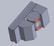
Have a lower die to grind, picture a 4” dia hardened D2 puck 2.5” tall with a 1.5” to 1.25” stepped bore in it. Inside bore, a hardened D2 bushing with a hat sits, hat is 1.499” dia and around 1.5” tall.

The face I need to grind is the side the bushing slips in from. On the bottom, bushing is about 0.020-0.030” from making contact with the mag chuck. Hence the question.

Is the mag flux enough thru the part to hold the assembly together? There are no other means.

Went down the thought process of parallels and stacking gauge blocks. Thought better to ask.
 
From experience with small parts, D2 does seem to exhibit lower magnetism/holding power on the chuck than other low-alloy or carbon steels. It has a fairly high chromium content, and I guess that might be what affects the magnetism somewhat.
So my guess would be that it won't hold well enough.
 
Mild steel block-ins on the go-side (the direction the part would go) with the contact high up on the part, a shim near the top edge of the block-in can work. A 123 block with the 2" set long way (long travel way), with a bump shim touching high on the part likely would be OK/good for a 2 1/2" tall part..

Pushing on the part with one hand palm should tell that it is safe.

Wet grinding is best to avoid a heat burn that could warp or stress a part.

Good to be quick to change wheels so you can quickly take stock with a course wheel and then skim with the surface finish needs wheel.

likely I would down grind (with the courser wheel) to take nearly all stock removal, and then incremental cross to finish.

*The touch/block high ( on the part) is important because an error angle on the block-in or on the part side so touching the part only at the bottom edge can cause a trip/tip over and poor block-in so making the part try to pull up off the chuck...an Ok bump shim might be .020 x 1/8 x 2".

RE: (Went down the thought process of parallels and stacking gauge blocks. Thought better to ask....NOT.

Wheels should be "Mount Up" marked so removing and replacing they will need less dressing, and if balanced will run closer to balance.
 
Last edited:
I've ground quite a bit of D-2, I was a die maker in another life. From my experience, if I had to trust D-2 to hold to the mag-chuck by itself I better find another solution. Some feel that D-2 sticks ok for light grinding. I never did because the consequences are too risky. I don't know what others are calling "light grinding" but die sharpening is almost always a minimum of .010 off and I don't have all day to take 14 x .0007 passes. If the workpiece can tip/slide it's got a good chance of doing so, seems even more likely when it heats up from grinding. To me, solid clamping/fixtures is the safer habit to be in.

Not able to visualize what you're trying to do (lack of imagination on my part) but a sketch/photo would help and bring better suggestions. Why does this have to be done in assembly? Could a V-block in a grinding vise (for perpendicular) accomplish this? Does the brim of the "hat" make it difficult? Don't understand what you're trying to grind. Visuals get details.
 
QTOP: the hat is 1.499” dia and around 1.5” tall.???
Sitting with only with that hat on the chuck?..so some one hand push pulls on the blocked -in part might help assure holding ability.
 
Last edited:
QTOP: the hat is 1.499” dia and around 1.5” tall.???
Sitting with only with that hat on the chuck?..so some one hand push pulls on the blocked -in part might help assure holding ability.

No, the 4” puck is on the chuck, the part with the step down/hat slides nicely inside the puck. The issue being when installed the hat/step down part does not contact the chuck.

I need to grind the top faces flush with each other. Sounds like doing each independently is the answer.

Ok here’s a photo of the old parts. The small stepped part goes into the larger part, ejector pin hole side down. When installed, that ejector pin hole face is short of being flush with the bottom surface. 577960F8-5F1C-496C-A235-3D702220A669.jpeg
 
Last edited:
I think it might not pull out, but it may spin. You've got a good seating depth so there's little danger of it coming up. It might decide to rotate in the hole though. Maybe a little CA when you stick it in the hole then a light tap on the opposite side to get it back out when done?
 
Why not just set the insert part directly on the chuck?...independently?
Taking 0.020-0.030” from a chancy setup may be better served taking all but .001- .003 with a good setup and just need a tickle grind being chancy.
Qt Eric..." but it may spin" is a serious concern..

Pressing it over a shim at the inner side is another option, perhaps.
 
Last edited:
Spinning would be no good. I’ll just grind the base and then match the insert. Insert will be held in a grinding vise.
-Just to avoid the consequences of anything happening (and the ensuing fallout from supervisor/co-workers) I'd grind both separately as you described. Time savings for grinding in assembly is maybe 1 hour? Nobody remembers when you try to cut an hour off the re-sharp but everybody remembers if it didn't go well. If this is a common repeat job there is a fixture that could be made to grind both in assembly but time/money have to weigh in.

I used to use a V-block in a grinding vise for holding round work like that to avoid excessive pressure from the vise. If the bottom "gap" is a known dimension I'd set that when holding the round in the V-block (ground spacer). Pull the vise off the chuck, set beside the larger plate/block on the surface plate and swing the DTI over both components to match. Micrometer reading optional. Just a suggestion.
 
AD, your point is well taken. I’m the cook and chief bottle washer at this location. Trying to get a job done quickly really clouds judgement- I suspected I was going down that road.

In tool room work sometimes there just ain’t a short cut. I appreciate the vice/part assembly note, quick clean way to check dims without disturbing the set up.
 
I’m the cook and chief bottle washer at this location.
-Which means nobody (except me...) is going to applaud your efforts to shorten the process. What wheel are you using? Got a VFD on the grinder? Slowing down the wheel speed (VFD) seems to improve grinding on hardened D-2. I presume that it hastens fracturing the wheel grain structure to expose fresh sharp edges instead of glazing/smearing the wheel, leaving burn/skid marks. Hope this was of some help. Ganbatte.
 
Last edited:
I believe the wheel is a 46H, grey aluminum oxide 10”. Grinder is a TOS automatic. Stout machine, set on the slower wheel speed. No burning on any D2 I’ve done. The process is dialled in.

I avoid using mist coolant but if it’s preferential I could.
 
I avoid using mist coolant but if it’s preferential I could.
-Only advantage to using coolant (IMO) is to keep the heat down. It does make a slurry mess that requires more careful chuck/part/fixture cleaning every time so that's an optional call per how much heat is involved. For heat control without coolant you can notch a groove in the center of the wheel (axial) with a Norbide stick (reducing wheel engagement width) or cut/grind 6-8 radial grooves in the perimeter of the wheel, creating an ersatz segmented wheel. These methods come at the expense of butchering a good wheel.

For wheels, this is also just an opinion. Sharp diamond dresser is a given. We used regular AO wheels for light/finish grinding. For heavier grinding exceeding .010-.012 we used the Radiac 4A-46 (red) wheels most of the time. There were a few Norton 5SG-46 (blue) wheels that did very well on coarse stock removal but didn't seem to finish grind as nicely as a freshly dressed one of the others previously mentioned. That may be all about my technique too, the SG wheels are good and held up well.

Soft/hard wheels is another subject for opinion. I didn't mind wasting a dressed wheel to get the majority of the stock removed, provided it wasn't wiping across the entire width of the wheel in a taper. Several variables to play with if a VFD is on the grinder to control spindle/wheel speed.

There's always the CBN wheels if the budget can handle it, they're my preferred although expensive. We also used CBN only in the jig grinder, I liked them.


RC Mech- If you already knew all this do pardon me for preaching to the choir. Perhaps some others might find something useful in this. Hope things are well for you and yours as 2022 shuffles out the door.
 
I think it might not pull out, but it may spin. You've got a good seating depth so there's little danger of it coming up. It might decide to rotate in the hole though. Maybe a little CA when you stick it in the hole then a light tap on the opposite side to get it back out when done?
That would have been my suggestion also. Use a gel version applied after the parts are pushed tightly together and then apply a debonder, followed by a solvent rinse after the parts are separated.

I once removed a stuck screw-off watch back by bonding a small piece of key stock with gel CA and then using the debonder. After solvent cleaning the back was clean and unmarred. I had to resort to this after attempts with a crab failed.
 
Is there a fit that would allow a shim to be placed in and secure the parts (anti-spin) together with a light press?
Are they going to be all different due to the amount of wear?
I would likely individually grind them in marked sets on the chuck so as to rough grind the perhaps .030 in the faster way, then assemble the parts with a locking shim/ or a reach-over clamp to the last .oo1 to .oo3 or so.
Likely use a depth micrometer because that is a fast way to measure and good for .001/.002.
I doubt that a vise will hold pars dead square, dead flush if that is needed.
 
Last edited:
Likely use a depth micrometer because that is a fast way to measure and good for .001/.002.
I doubt that a vise will hold pars dead square, dead flush if that is needed.
-Not to be contrary but the part can be held square in a grinding vise. It depends upon the reference surface(s) and how accurate those have been ground. Accurate grinding of vise and V-block when made is a given. Three examples below for using either the larger OD or the undercut as the reference. I prefer using the V-block when possible. Verification on the surface plate w/DTI is required before grinding. As for .001/.002 that's often enough to "print" on the final part, less is usually preferred or required.
 

Attachments

  • V-B-S.JPG
    V-B-S.JPG
    47.2 KB · Views: 7
  • V-B-S-2.JPG
    V-B-S-2.JPG
    44.1 KB · Views: 7
  • V-S.JPG
    V-S.JPG
    40 KB · Views: 7
Last edited:
I would be inclined to agree with Buck, with the part geometry being what it is. It doesn't have equal diameters at either end, but instead steps down smaller along its length. So like Buck said, maybe, maybe not. Tough to hold in a vise dead nuts with a shape like that. Might work, might not. Might depend on how close it needs to be.
 
Certainly not worth an argument or hard feelings, a skilled guy like AD can make good use of a vise and hold .001 and possibly .0002.

The problem with a vise is that the tightening screw will often distort the device and cause some errors, and the moving jaw likely is not dead parallel with the solid jaw.

Chunky V blocks and angle plates with C or parallel clamps are not subject to this distortion caused by the tightening screw....mostly caused by over-tightening.

The error of the moving jaw not being dead square can also give less than good holding pressure on the part..
.
 
Last edited:


Back
Top