What's new
What's new

Grounding machines?

Our site is 22 acres of workshop. grounding is covered by an earth grid with multiple ground rods within and outside the buildings, all connected together with all of the structural steel work and pipework. These are connected to the neutral/star-points of the two substation secondaries that feed the site. All electrical devices are earthed, as are all non-electrical steel work.

We don't get electric shocks or interference...

Do it properly according to your local code.
 
In the US you will find that virtually all 3 phase transformers are Delta on the input side and Y on the output. The reason is to prevent direct one to one coupling of noise from primary to secondary.

This is true, most are delta primary and Y secondary.
However the problems begin when you try to use it in reverse, as many try to do.

In reverse, the Y becomes the primary, and the Delta becomes the secondary. Then your left with 2 choices for the output, neither of which is ideal for powering most standard drives.

1) Ungrounded delta - never a good choice. Doesn't provide any fault current return path or connection to the building electrode system. Can be very hazardous to operators and equipment.

2) Corner grounded delta - Provides a fault current path for short circuits to clear. Also provides a non symmetrical output, with respect to ground, which is very hard on drive electronics designed for a Y input. Input MOV's (surge suppressors)and solid state devices can become damaged.

Corner grounded systems are nonstandard today and most folks don't understand how to terminate them or troubleshoot them. It's best to avoid this method for any drive system if you want it to last.

SAF Ω
 
This is true, most are delta primary and Y secondary.
However the problems begin when you try to use it in reverse, as many try to do.


SAF Ω


OK, since we've left the OP's question long time ago, I will ask the question why you think that MOST 3ph transformers are Y secondary?
And while we're at it, why would anyone attempt to connect a Delta/Y transformer in reverse, that is to say have a Y primary?

Sure, most of the 277/480 services are Y, and also most of residential/commercial/light industrial services are also 120/208 Y.
But, for most industrial installations it is ( in my experience anyway ) more common to find a Delta supply from the POCO, and then a locally installed
additional transformer for 120/208 supply.

Now, if you are talking about transformers that are installed in most of today's CNC equipment, then yes, Y secondary is by far more desirable, but that has
nothing to do with the OP's question.
From my view, as far as the incoming service is concerned, all CNC equipment ( or anything else for that matter ) is a purely 3ph load, regardless of
what type of transformer is installed in them.
And, as such, the grounding is identical to all installations, that is to say a separate, dedicated conductor running from equipment all the way back to the service's ground
point, regardless of where that's derived from.
 
I originally said MOST because I've been working with electrical equipment nearly 50 years now and have worked on lots of ungrounded Delta, Open Delta and other systems. The power companies often use 3 separate transformers rather than one large one, delta connected on the primary and Y connected on the secondary. The advantage of 3 transformers for them in the old days was that for sites that needed mostly single phase and a little 3 phase they'd install one tiny transformer for the third leg. These 240 volt systems were often open Delta with the so called Red, or Bastard leg. Bastard leg because it was 208 volts to ground, and hurt like hell if you touched it!

The reason some people use a transformer in reverse is because they have 208 volt power and have piece of equipment that needs 480 volt. You are correct there is no safe way to do that as the transformer won't even have a center tap on the primary for a neutral connection to ground. If you need 480 volt power from 208 you should use three single phase transformers connected Y to Y with a grounded neutral.
So we are back to that grounding question.
 
Every machine I've seen installed and I've seen alot (3-5 a year, every year for the last 9 years)has been grounded both with a separate ground rod and to building service ground.

In an area with lots of lightning this could prove to be a very bad practice. The guy with 22 acres tied to a low impedance grounding grid is about as lightning resistant as possible.

The problem with your ground rods is that they go into soil that is a poor conductor at best. Lightning has an enormous voltage that can be in the millions of volts. A lightning strike on the ground outside your building flows in all directions. If it gets to your service entrance ground first it might be at 500,000 volts or more. Traveling through the earths high resistance it might drop to 400,000 volts when it reaches the machine ground rod. You suddenly have a 100,000 volt surge going through your machine!

I build waste treatment plants with underground tanks, often a few hundred feet from the building with our equipment. We get struck in this way all the time. One plant struck 3 times in one month with damage each time! Ground wires not ground rods are your friend.
 
SeymourDumore,

The reason I bring up the transformer connection issue for CNC equipment, is because I encounter these types of problems regularly in my field work. Not just with metalworking CNC but also many other types of equipment that use electronic controls and drives.

Many CNC vendors specify that the customer must provide an isolation transformer in order for the warranty coverage to be in effect. As soon as you interject a isolation transformer into the feeder to the equipment, that changes the grounding scenario. That was the subject of the OP to ground or not to ground?

Many customers and their plant service people do not understand the differences of the different types of systems, and are of the belief, that you can use any transformer that they may have handy or available used, to change the service voltage to match the equipment voltage. But ignore the requirements of bonding the output coil,to the building service electrode system, usually due to lack of understanding.

Sure, there are many types of 3Φ transformers available but the most common ones used, are for stepping down from higher voltage to lower utilization voltages. Normally delta to Y. It is when these types are re-purposed to go up in voltage, is when many run into trouble. This often happens in smaller commercial shops where the operator has a 208 or 240V service and purchases a used piece of equipment that requires 240,480 or 400V.

From my view, as far as the incoming service is concerned, all CNC equipment ( or anything else for that matter ) is a purely 3ph load, regardless of
what type of transformer is installed in them.
And, as such, the grounding is identical to all installations, that is to say a separate, dedicated conductor running from equipment all the way back to the service's ground point, regardless of where that's derived from.

I would disagree that all machine loads are purely 3Φ. Many indexing drives and other other internal equipment can be 1Φ.

I will also disagree that all grounding requirements are identical when a isolation transformer is involved. The code and good practice demands that the output coil of all isolation transformers be solidly bonded to the building electrode system for fault current and electrocution hazard prevention.

To give an example of what I'm talking about, have a gander of this recent thread, from one of the regular forum members.

http://www.practicalmachinist.com/vb/transformers-phase-converters-and-vfd/how-can-machine-ground-affect-welding-arc-325892/

He is doing things the way your suggesting. A dedicated isolated ground conductor run from the CNC equipment, to the transformer frame and on to the service equipment. He is experiencing problems of an unusual type. But unrealized to him, is that the machine frame is not bonded back to the source of energy, the delta output coil of his reverse connected transformer. Much worse than his welding problem, is the fact that his equipment does not have a low impedance equipment grounding connection for fault currents back to the source (isolated delta coil). This can be a serious hazard when something on the machine faults to the frame, even though the machine operates properly and is connected to the service system ground.

I come here to learn first and second to share knowledge. I can be easily persuaded to butt out, if my contributions are not welcome.

SAF Ω
 
I come here to learn first and second to share knowledge. I can be easily persuaded to butt out, if my contributions are not welcome.

SAF Ω

Not my intention at all! Just like you, I ( and hoping that most of us ) is coming here for the very same reason.

Regarding 3Ph comment.
If the machine has a 3PH transformer in it, then it IS a purely 3PH load as far as the service is concerned.
Internal imbalances notwithstanding, you will never ( other than perhaps a few unique situations ) run a Neutral wire to the equipment, therefore
from the perspective of the supply, it is a pure 3Ph load.

I will also disagree that all grounding requirements are identical when a isolation transformer is involved. The code and good practice demands that the output coil of all isolation transformers be solidly bonded to the building electrode system for fault current and electrocution hazard prevention.

Which means in short terms is that the equipment must be bonded to the building's ground system according to code ( and not via a ground rod), while hoping that the manufacturer
has properly connected the internal ground points.
That last tidbit I've added as I have had to chase my tail with an EDM drill from Taiwan.
 
Grounding and bonding- one of the most misunderstood sections of the code and practical application. It's always a difficult subject of conversation.

Many would like to believe it is as simple as one and done, and often can be, given the right conditions. In reality, it can also be quite a bit more complex than many realize, depending on the site conditions.

Grounding and Bonding covers several different protective functions simultaneously, as well as reducing noise and stray currents on the supplied equipment.

Previously in this thread, posters covered the subject of grounding equipment, to the service source, and bonding to the earth electrode system. The discussion is missing the fault current flow path, especially when a isolation transformer is used to adjust voltage levels. Fault current flow is one of the most important aspects to a properly grounded system. It should never be taken lightly.

This is the reason I even bothered adding the post about, grounding isolation transformer output windings. Without a bonded ground connection to the output winding, you would be essentially running the load without a low impedance fault current path. Even though the other aspects of the grounding system would be covered properly.

It sounds to me that GaryHLucas has a good grasp of the concept, of what I was trying to get at. Maybe he can frame the concept in different, more understandable verbiage, better than mine?

SAF Ω
 
Hello Fredc,
You just reminded me of an incident 37 years ago in Gardena, Ca does anyone remember Chalco Engineering?
otrlt
otrlt,
I can not even remember the name of the outfit. It seems that engineering was part of the name but this place was in Center Point, Texas. They were doing contracting for a big Westinghouse plant, mostly fabricating large weldments. Most of the accidents that the supervisor walked to were in the fabrication department. I do not think he even knew about my "experiences".
 
To give an example of what I'm talking about, have a gander of this recent thread, from one of the regular forum members.

http://www.practicalmachinist.com/v...can-machine-ground-affect-welding-arc-325892/

He is doing things the way your suggesting. A dedicated isolated ground conductor run from the CNC equipment, to the transformer frame and on to the service equipment. He is experiencing problems of an unusual type. But unrealized to him, is that the machine frame is not bonded back to the source of energy, the delta output coil of his reverse connected transformer. Much worse than his welding problem, is the fact that his equipment does not have a low impedance equipment grounding connection for fault currents back to the source (isolated delta coil). This can be a serious hazard when something on the machine faults to the frame, even though the machine operates properly and is connected to the service system ground.

I come here to learn first and second to share knowledge. I can be easily persuaded to butt out, if my contributions are not welcome.

SAF Ω

So how would you connect a low impedance ground back to the delta coil in that circumstance?
 
So how would you connect a low impedance ground back to the delta coil in that circumstance?


With a separate zig-zag transformer winding to give a star/wye point than could be grounded. Slightly over the top, but such things do exist where there's no other solution.

I use a similar setup to give me a grounded neutral on the VFD/invertor that feeds my workshop 3ph supplies. It allows me to both earth reference the supply and to correctly feed the single phase control circuits of the machines. A star/wye output from the VFD would save me from running a 150lb transformer for this simple purpose.:(

Search for neutral earthing transformer on the Interwebs. Usually used for big installations, but the theory works for little stuff as well.
 
Mud,

The only way you could do it with the transformer you have is corner ground it.

That means intentionally connecting one of the output legs to your ground conductor.

As it sits now, a fault on your machine does not have a way for the fault energy to get back to the transformer output coil, in order to trip the breaker or blow the fuse.

The problem with corner grounding it is, the drives on your CNC are not going to like it. If you take a look at just about any well documented drive manual, it will tell you not to use a corner grounded delta or on US manufactured drives, tell you how to remove the MOV protection to make it suitable for use with corner grounded systems.

The real solution is to replace the transformer with one that has a Y output. Even then the center of the output Y (XO or H0) needs to be connected to your grounding conductor.

Take another look at the sketch I made for you. Look at the output winding. It has no dedicated connection to the ground system. For any fault energy to get back to that coil, it must travel through your ground conductor to the service, then back on your premise wiring, to the input winding. Once back to the input winding, it must travel across the magnetic coupling to get to the output coil. That represents a high impedance path that is likely not to trip the protective device when you really need it to.

Realize that fault energy must get back to it's source, in order to trip the protective device. The source in your case is is the delta output winding. The output winding is coupled only magnetically, it has no low impedance connection. The code refers to it as a separately derived system. And requires that all separately derived systems be bonded to the earthing system as well.

Fault energy does not want to go to the earth, or the utility system transformer. It is seeking that output coil. Some will flow to the earth and the utility transformer, but not enough to trip the protective device rapidly as it should.

Corner grounded systems are OK for machinery that has electro-mechanical controls and motors, but most solid state controls are not built to deal with it. Solid state controls want a symmetrical Y system supply.

I'm happy that your here reading this information, before something bad happens. That's what I was trying to do in this thread, is warn others as well. It's subject matter that is not well understood. Just trying to share the knowledge.

If you change out the transformer and properly connect it, your welding problem should be long gone. It's a good thing that you posted about your welding problem, that was the trigger for getting more informed.

Stay Safe, SAF Ω
 
Finding a 240V Delta to 480V Wye Transfomer

Mud,
I did a search on ebay to find a replacement for the transformer you need. After 500 listings (50 x 10pages) there was only one that I found with a 480V Y coil for your output and a 240V delta coil for your input. It is a 480 Y primary to a 240V delta secondary. It could be reverse connected as your doing now and work fine for your application. The price is right, but it's on the other side of the country from you.

SQUARE D EE45T151HCT 48Y 24 45KVA TRANSFORMER 45 KVA | eBay

s-l1600.jpg


For SeymourDumore, this is what we meant earlier about most units being HV delta/ LV Wye for common units. 500 listings and only one unit suitable, and even it needs to be reverse connected for Mud's application. I would consider that means most, not that other units don't exist, but their expensive new, and like hens teeth used.

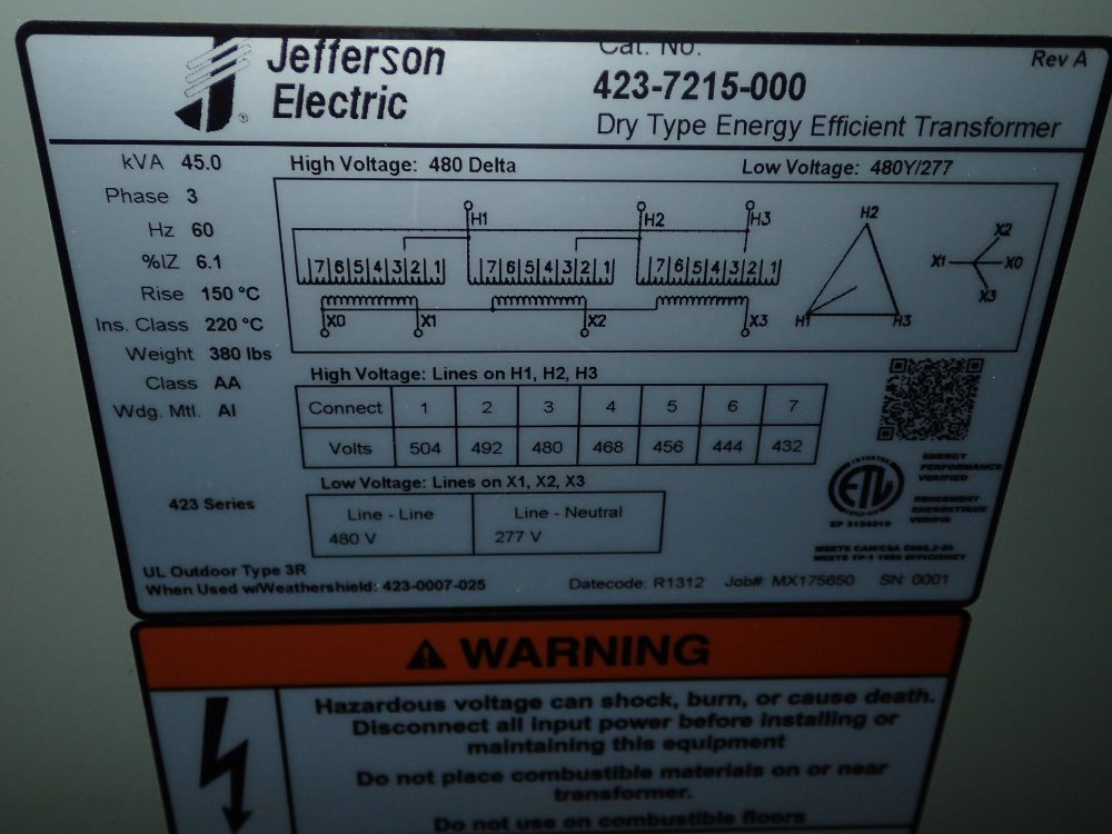
There were several units that were HV 480 Delta/ LV 480/277 Wye and I'll link to some below. Using one of these units would work, but then you would need to use 2) 3Φ transformers inline. The existing one to step up the voltage, and the second one to derive the Y output. That's a lot of buzzing iron to have around and more losses on the utility bill. The 480 delta / 480Y are a little less rare in the used market, because plants would use these to go from a 480 3 wire busway to a 480Y CNC load. It's a little more common application.

One other thought. If your machine has a internal Y auto-transformer with adjustable taps suitable for 208V input, you might be able to more easily find a transformer with this rating. Namely 240 Delta Pri / 208 Wye Sec. This version may be more available used as well.

Does your machine really require a 45KVA unit? There may be other choices available in smaller units.

JEFFERSON ELECTRIC TRANSFORMER 45 KVA 1 | eBay
20160819125027259_L.JPG


SQUARE D SORGEL 33749-5132-3 CLASS AA 48-48/277V 45KVA TRANSFORMER 45T76HB | eBay

GENERAL SIGNAL HEVI-DUTY 45KVA, 46 TO 46/266VAC, 3-PHASE TRANSFORMER DT651H45S | eBay

GE 45 kVA 48 Delta 48Y/277 9T23Q9853 3PH Isolation Dry Type Transformer 45kVA | eBay

http://www.ebay.com/itm/SQUARE-D-45-KVA-EE45T1814H-THREE-PHASE-480V-PRI-480-277V-SEC-TRANSFORMER-/122154872516?hash=item1c70ff6ec4:g:AKgAAOSwCGVX6ubK

http://www.ebay.com/itm/GE-TYPE-QL-60HZ-3PH-480-TO-480-277V-45KVA-DRY-TYPE-TRANSFORMER-9T23B3853-DENT-/311502940238?hash=item488705a84e:g:yLIAAOSwpDdVbasf

http://www.ebay.com/itm/Westinghouse-Class-AA-Three-Phase-Transformer-45-KVA-V48M47T45F-480-Del-480Y-277-/161457581368?hash=item25979f2d38:g:mekAAOSw8cNURWZa

SAF Ω
 
I think it is shameful that this information is not in the public domain.
Well it is. You could have bought it off the link you referenced. Your just complaining that it's not free. It is public domain, you just have to pay for it. Stops Harry Home Shop twisting their own wires.
 
^ yeah but the reality is it does not, that said most of the worst wiring i have encountered is generally done by people who would not even read the stds if there were free and sitting in front of them. Personally i think if you want everyone to conform to a std and the state at any level wants you to conform to it, then it very much should be freely available and in the public domain, other wise its akin to saying to someone im going to bust you for breaking a law you were too poor to afford to know the details off.

As to corner grounded delta, seams a odd way to go, but thats just my take on it, but then you Americans seam to love your odd 3 phase approaches. Over here three phase star s the std approach, yeah you may connect motors delta, but pretty much zero electronics goes that way, they all go single live to neutral. With neutral nominally being tied to ground at the one fixed point.

That said we seam to have grounding tied up a lot tighter in the regs than you lot do, its a very detailed subject, it has to be designed in and wire lengths considered and its not unheard of for ground conductors to have to be larger than the current conductors in CSA to insure large trip currents to guarantee fast fault trips especially on three phase supplies.
 
Regarding 3Ph comment.
If the machine has a 3PH transformer in it, then it IS a purely 3PH load as far as the service is concerned.
Internal imbalances notwithstanding, you will never ( other than perhaps a few unique situations ) run a Neutral wire to the equipment, therefore from the perspective of the supply, it is a pure 3Ph load.

Never need a neutral? Well if you consider it, that dedicated insulated ground wire is the same thing really as a neutral conductor. Connects to the same place at the service, has different color tape / insulation, at the load end it connects to the frame, instead of a neutral bar.

The actual conductor is the same, other than the load termination point. The functions provided by each is entirely different. The dedicated ground is for fault current, only flows current during a fault. The neutral would be for unbalanced operating current, carries normal unbalanced operating current.

Which means in short terms is that the equipment must be bonded to the building's ground system according to code ( and not via a ground rod), while hoping that the manufacturer has properly connected the internal ground points.That last tidbit I've added as I have had to chase my tail with an EDM drill from Taiwan.

Don't hope that the manufacturer from Taiwan or elsewhere, properly bonded the machine, ENSURE that they did, and did it correctly. Ensure that the guy that touched it before you didn't bung it either. Lives matter.

Asian countries may use a slightly different distribution system than here in the US, so the bonding connections can be slightly different. Sometimes they can come with an isolated (insulated from the frame) ground bar for the controls, but need a bonding connection for the frame (the fault current connection again).

SAF Ω
 
Mud,

On closer inspection, that first unit I found with the Y 480 coil, that will not work for you.

The transformer does not have the center terminal (X0) brought out to the terminal strip. Its the right type, but missing the actual terminal point. Missed that on scanning 500 ads.

SAF Ω
 
The National Electric Code is superseded by the Authority having jurisdiction. If the local government has accepted the NEC then I would recommend you obtain a lawyer, sue the company for everything you can get for putting your life at risk. If you walk away with heaps of money and become the new owner, ground the equipment to protect the safety of you and your fellow employees. May the idiot who operates ungrounded equipment end up as a homeless person freezing in Millinocket, Maine and that would be too good for them.


Back
Top