jordan6679
Plastic
- Joined
- Feb 14, 2014
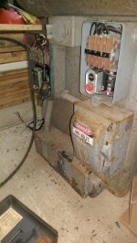
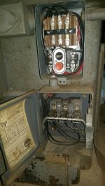
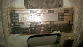
Would anyone know if a service manual was available for the older model? Also I have the M head, what collet fits the spindle? It sure is a small. Another question for you all, I posted a picture of the power box and the ratings this mill can handle. It states 3hp on 220 single, and 7hp on 220 3 phase. Can anyone confirm these? I'm am just getting into home machining and want to get this vintage beauty running smooth.