What's new
What's new

Help with drum switch wiring Please!

spooky

Aluminum
Joined
Nov 4, 2010
Location
West Virginia, USA
Hey All,

I'm swapping out the 3ph motor in my lathe for a single phase. I am in a temporary shop for the next year w/no 3ph access.

Per JST's sticky thread on drum switch wiring I did do a search and didn't come up with this combo

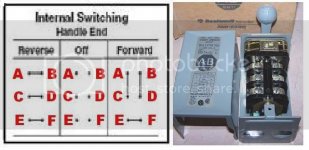
-the drum switch is a Allen-Bradley 350-TAV32. Unfortunately the schematic on the lid is too degraded to read. I tried to find one online to no avail.

-The motor is a Century C319 single phase, single voltage 220

-The motor has 2 capacitors on top. Again I couldn't find a wiring diagram on Century's webpage for this model. It is essentially a 4 wire motor (see pics below)

centuryc319.jpg

centurywire.jpg

drumsw.jpg

If anyone can help with this I'd be most grateful!

Thank you,

Chris E.
 
Sorry. most of the active members are too busy squabbling over politics.

First off map out how your switch works, without that you will not understand how to wire it, I suggest drawing it out on paper, 2 diagrams, one for either way it is engaged. Next draw out the wiring for motor in forward, then again for reverse. Set the 2 pieces of paper side by side and stare at it until it makes sense and you have an ah-ha moment. Hint you will have to run a couple extra wires from motor to switch. No, I don't have a diagram to hand you.

Thank you. That has been my process so far. I feel like I'm trying to put a puzzle together with a few pieces missing!
 
Having 2 Capacitors means nothing to connection. One is a Run Cap. and is connected to the start winding all the time. The other is the start capacitor that is connected to the start winding thru a centrifugal switch which will disconnect the capacitor at a preset speed at the point it is no longer needed. The run capacitor simply uses the start winding to add HP.
The drum switch will have a means to reverse connection and will use 4 terminals and another to make a connection no mater which way the handle is turned and open when the handle is in the middle. (2 terminals)
You simply have to check out which terminals do what. A good photo of the drum switch wiring diagram will help.
Motors with a single capacitor will not reverse when the motor is above the speed of the centrifugal switch so that after the motor is started flipping the switch to reverse when the motor is above switch speed will do nothing. I'm not sure what will happen when a motor with a run capacitor is switched to reverse while the motor is at near full speed will do, it may eventually destroy the capacitor or the start winding.
You can get started, wire the motor and get more information from the Motor Gurus here about running the motor when after starting flipping the switch to reverse.
 
Still no joy.........

I contacted Regal Rexnord (Century) twice to try and get a wiring diagram that shows the P and T numbers for the wiring. No reply yet...

On the post/link that SAF shared above I did find this drawing
1.5hpcentury.jpg
which is pretty close to the motor I have, but different colored wiring. Also I cannot decipher the connections on the drum switch drawing. It looks like it has 12 connections.

I am going to contact the electrical house where I bought the motor and see if they have the wiring drawing. Oh and I was able to get enough crud off the cover plate of my drum switch to find out that it does connect like this..
allenbradley350sw.jpg
again from SAF's shared post above.
 
Combine these two, and you should have it.
Dayton 1HP 230V FurnaceR44.jpg

1Φ 230V Century.jpg
 

Attachments

  • centuryc319.jpg
    centuryc319.jpg
    65.8 KB · Views: 18
Well, I went back to the shop where I bought the motor and the owner helped me figure it out.

Like the guy in the thread that SAF shared above, I have a segment in my set up that is always hot. I am not too worried about that as there is a main power disconnect on my lathe. And the twist lock plug is within reach too.

I do appreciate all the replies though!

CE
 
Yep, folks do get upset about that hot wire deal , even though they have an OSHA suitable disconnect plugged into the outlet.......

There is a theoretical hazard that the motor could get connected across half voltage if the wrong wire came loose and touched ground.
 
If you can get into the motor wiring there's an easy way to solve the 'always hot 240 volt' problem.

wire.jpg


Trick only works on dual voltage motors, where one end of the start winding is tied to the mid-point of the run windings. Selecting which hot leg it ties to, determines direction.


Back
Top