What's new
What's new

Hilger & Watts TA51-2 autocollimator

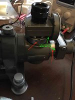
I have been unable to unscrew the attachment rings (red arrows below) to remove the reticule and target subassemblies. Dennis proposed an obvious reason and solution: the screws (green arrows/text) are locking screws. Can anyone here confirm/deny? The screws have peculiar locking collars, so I'll need to make a tool to manipulate them. I can't just loosen them to immediately assess the effect .

IMG_8198-1-new.jpg
 
Last edited:
I can now answer my question from the previous post: the screws are NOT locking screws for the threaded rings. Instead, if those screws are loosened, they permit the mounted object to rotate. When tightened, they lock the rotation. This means that the target can be rotated until it is properly oriented with respect to the autocollimator body, and that the reticule can be rotated until it is parallel to the target lines.

To make these adjustments, a tool is needed to loosen and tighten the locking collars. I made a tool from 8mm hex stock (free-cutting steel).

IMG_8269-new.jpg


IMG_8273-new.jpg

Overall length is 36mm, diameter is 5mm for the first 20mm, then 5.6mm for the next 6mm. The hole at the tip is 2.8mm diameter, and the prongs are 0.8mm wide and 0.8mm high.
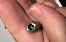
IMG_8270-new.jpg
I broached a 5mm hex into the wide end, so that it can be turned with a hex driver

IMG_8274-new.jpg
The Id of 2.8mm at the tip is to center it on the screw, but most of the ID is 3.5 mm so that there is a bit more clearance for a screwdriver inside

IMG_8272-new.jpgIMG_8271-new.jpg

This made it simple to rotate the reticule mount so that I could align the crosshairs parallel to the target. You can see that these are not perfect. If you look at the vertical parts, it appears that the reticule (outer parallel lines) is rotated slightly CCW with respect to the target (inner crosshair). But if you look at the horizontal lines, it appears that the reticule is rotated slightly CW with respect to the target. I don't know if this is optical distortion or imperfections in the target or reticule.

IMG_8275-new.jpg

Apologies for the poor quality image, this is with my cell phone.

This is one of those instances where it takes a couple of hours to make the tool that is needed, and five minutes to do the actual adjustment. I'm sure that one can also buy a tool for this. The metric standard fot these threaded collars ("slotted round nuts") is DIN 546, and one can buy pronged drivers and bits for these. I'm not sure about the British Association equivalents.
 
Last edited:
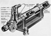
I have not been able find any kind of Hilger Watts service manual for these autocollimators. However I discovered that pages 23-25 of the book by K.J. Hume, "Metrology with Autocollimators", published by Hilger and Watts in 1965 have a detailed description of the adjustment procedure. It also has a nice cut-away diagram, which I am reproducing below.

Screenshot 2023-01-25 at 13.05.43.jpg


The section on adjustment starts like this:

"From what follows, it must not be thought that every user of an autocollimator should be his own optical adjuster. The user is advised to leave instrument adjustments alone if the instrument is working properly and shows correct calibration when checked with the necessary accurate equipment. Even if some adjustment is necessary, normally only due to some accident or deliberate interference, it is best to let the manufacturers or their accredited agent do it, or, if this is impracticable, at least to make sure that the person undertaking the job understands the instrument and has proven skill in such matters.

There may, however, be occasions when it is essential for such a skilled, but not specialized, person to adjust an autocollimator and, in such a case, the following information intelligently applied will serve as a guide. It will also help the reader to understand more of the principles on which an autocollimator is constructed. No detailed instructions will be given for actual mechanical adjustments; these would be out of place here."

Needless to say, this is very helpful for people like me.
 
Hello! Do you have any problems with the autocollimator type TA 53. The wires on the connector on the vibrator type FA 70S fell out and I am not sure that they are connected again. The vibrator cannot receive a signal from the autocollimator. FA 70S. Sorry for my bad English, I hope you understand what the problem is. Thank you
 
Hello! Do you have any problems with the autocollimator type TA 53. The wires on the connector on the vibrator type FA 70S fell out and I am not sure that they are connected again. The vibrator cannot receive a signal from the autocollimator. FA 70S. Sorry for my bad English, I hope you understand what the problem is. Thank you
I have a TA51 not a TA53, but see that Dennis is trying to help you. I suggest you take a couple of photos to show the problem and post them in the thread where Dennis is helping you.


Back
Top