What's new
What's new

Homemade Pneumatic Collet Closer - Help

Brian.M

Plastic
Joined
May 3, 2021
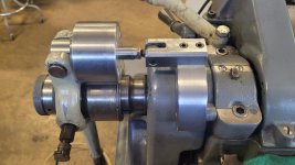
So I have tried to make my lever style 5C collet closer pneumatic. So far this is what I have, it opens and closes fine and runs, but there must be tension/force somewhere I had not accounted for. I remove pressure from the cylinder while running, but while trying to drill a 3/8 hole in mild steel the lathe slows to a stop. Best I can figure is I need an added angle of movement on the fixed end.

Anyone done something like this before? Hadn't seen any when I searched the forum. If you have could you share how you did it, or what your thoughts are on my setup?


Also of note: Trying to put as few holes in the lathe as possible. Only one so far...
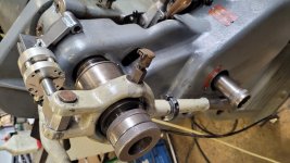
20220301_141416.jpg 20220301_141430.jpg 20220301_141447.jpg
 
You are holding a 3/8 drill in a collet and drilling a workpiece in a milling attachment? Your lathe is slowing down instead of breaking the drill?
 
With both ends of the lever tied to the lathe frame, all the force applied to it tries to pull the spindle out of the machine, against the thrust bearing. Add the drilling force, and clearly it is too much for the lightly designed spindle thrust bearings.

Although there may be a reaction rod to keep some parts from spinning, air closers only create actual longitudinal force between the spindle itself, and the drawtube. The spindle can still float with whatever clearance was last set.

A manual lever closer as you have started with, initially induces force between the spindle and frame, but locks over center and then floats unless the operator continues to (unecessarily) pull on it. Even in that case,(s)he will not induce the type of force the aircylinder is likely adding.

For the system you connived, it would be possible with a little air-logic (perhaps a 4 way aircontrolled valve and another air controlled 3 way; but i don't want to work on your project enough to design the circuit. Look online), or a pressure or position sensor to the cylinder or the other end of the lever, to create an automatic cycle that with one input (lever to "close" position) would set the closer over center, then dump the air pressure but not apply reverse pressure; yet create the situation to put air to the correct side of the cylinder when you move the lever to "open" the collet. This assumes a double acting aircylinder, not one with spring return.

Better & more compact might be re-designing your system for one that hangs completely on the spindle except a floating torque rod.

smt

Thank you for your detailed and constructive response.

This is still pretty early stages, and I was planning on adding a center exhaust valve on a 2 position momentary switch. That way it would close then not continue to put pressure on the draw tube after it locks.
 
I added another linkage at the fixed end seems to have taken care of this issue. Will update as the project is completed.

20220304_145659.jpg
 
This is still pretty early stages, and I was planning on adding a center exhaust valve on a 2 position momentary switch. That way it would close then not continue to put pressure on the draw tube after it locks.

That is certainly a simple logical method!
I assume that the initiative for pneumatics was for speed?
Will the pneumatics interact with other parts of a cycle, such as an automated bar feeder?
Stand-alone, the total ergonomic package needs to be faster/more intuitive than manual lever op or is it worth doing?
Fun project, either way.

smt
 
I assume that the initiative for pneumatics was for speed?

What prompted me to get this going was modifying 500 parts which needed 2 operations. Opening and closing the lever 1000 times was quite slow and very much a real pain in the ass... or shoulder more accurately. Also made a 5C collet stop/ejector.

Will the pneumatics interact with other parts of a cycle, such as an automated bar feeder?

I would like to add something like that, not entirely sure how I would do that though. Seeing as this is not necessarily a production machine (making small parts for around the shop and modifying existing parts) I just can't justify spending a ton of money on off the shelf products.
 
I have an Alfred Herbert air chuck that has the air chamber inside the chuck ,and so has full spindle diameter clearance .....The normal way of air application is to have a pancake cylinder mounted on the rear of the spindle ,pulling or pushing via a rod ,or hollow rod....this applies no loading to spindle bearings,but requires a rotary air connector.
 
I have an Alfred Herbert air chuck that has the air chamber inside the chuck ,and so has full spindle diameter clearance .....The normal way of air application is to have a pancake cylinder mounted on the rear of the spindle ,pulling or pushing via a rod ,or hollow rod....this applies no loading to spindle bearings,but requires a rotary air connector.

Yeah I had considered that, probably would have preferred it, but had little luck finding something I could connect to my lathe while modifying it as little as possible.
 
I have an Alfred Herbert air chuck that has the air chamber inside the chuck ,and so has full spindle diameter clearance .....
SMW also made those, maybe easier to find. I had a 12"-er but prefer hydraulic now. Air is too elastic, it doesn't control jaw perssure as well. It's fine for thickwall or solid but if you have parts you want to hold but not crush, air doesn't work as well.
 
Just an update from my prior proof of concept setup.

Added an arch to span over the rear guard, using the guard mounting holes. Added larger cylinder with a housing/clevis. Still a work in progress, need to get controls set up.

20220311_120358.jpg20220311_120409.jpg20220311_120654.jpg20220311_122520.jpg20220311_121942.jpg


Back
Top