What's new
What's new

How to design/machine receptacle for hydraulic fitting?

ballen

Diamond
Joined
Sep 25, 2011
Location
Garbsen, Germany
For a one-off project, I need to attach this hydraulic pressure gauge to a chamber in a steel block. The steel is free-machining, unproblematic. Inside is hydraulic fluid, at pressures up to 400 Bar. How do I design the receptacle that this screws into?

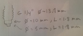
IMG_3911.jpg IMG_3912.jpg

The thread is a parallel (non-tapered) 1/4" metric G (Whitworth British Standard Pipe Parallel) intended for strength, but not to seal. So the seal must come from one of two places. Either the short 5mm brass stub should be forced into some type of taper, or the 10mm flat must bear against a trapped sealing washer or o-ring. In either case, I can't just drill an 11.8mm hole and tap it.

One last issue, I would like to be able to orient the gauge in a particular direction. So I presume that the last fitting step will be on the mill, where after screwing and tightening the gauge into place, I calculate how much deeper the faces for the 10mm and the taper for the 5mm stubs should go, then shave off the correct amounts.

I don't have much experience with hydraulic stuff, other than knowing that if the seal isn't well designed, under 400 Bar of pressure, it will leak.

(Don, if I have started this thread in the wrong forum, please move it to the right place.)
 
I am not familiar with the fitting on your gauge. I wonder if it might match some European hose end or tube fitting, perhaps for automobile hydraulic brakes.

In the USA, we have a style of high pressure fitting called O-ring boss. There is a parallel thread and, in the case of needing adjustable orientation, an O-ring, flat washer and jam nut. Of course, the threads are inch-based. http://pressureconnections.com/customer/prcoco/customerpages/literature/Steel_O-Ring_Boss.pdf

Anyway, I suppose you might make a brass adapter with a female thread to match your gauge and seal it with permanent Loctite. The other end of the adapter could be a tapered pipe thread or an O-ring boss style with European threads.

Larry
 
does an o-ring really seal 400 bar?

Sure. The tolerances, finishes, and composition become more important as pressures increase but 10,000 psi is no problem.

That short spud on the end of the gage makes me think there is a dedicated tube fitting for that gage.
 
For a one time job a standard O ring of "2 mm and a bit" section sat over the little nipple working onto a flat face will go just fine at nice hand tight. PTFE tape wrap on the threads too. Not to hold pressure, just for nicer fit.

When I was working with dry air high pressure sytems to feed JT coolers we used to buy in the special, dry packed, made for the job O rings at around £5 a pop but there were occasions when ordinary ones got substituted and hafta say that I never saw any difference in performance. Despite giving the substituter a torrid time of it after spotting the change. Its surprising how little tightening force is needed to hold the high pressures which is why all my newbies got a "don't do as I do do as I say" demo on a carefully set-up system with lots of pressure and minimal air volume.

Clive
 
That appears to be a common adapter fitting for gauges and the like, I had a kit of different gauges that we could hook up to our pumps on the machines we built, hooking up under no pressure, of course. I think there just supposed to be a copper washer on the end creating the seal? Dedicated fittings for these gauge adapters come in metric, SAE O ring face seal, and pipe fitting. Least thats what we had available to us.

Parker EMA3 Series Couplers

upon looking at the picture on this page the seal looks to be internal rather than the copper washer I mentioned. It has been a while singe I seen one, please forgive my faulty memory.
 
Everyone, thanks for the helpful replies. PM is great for things like this.

Limy Sami, the picture you pointed me to on the first page here pressuregauge.co.uk - Pressure Gauge Manufacture and Supply absolutely nails it -- it is exactly my fitting and application. I need a flat compression washer with a 5mm ID and 10mm OD, that sits on the nipple and gets compressed when tightening. I searched for sealing washing EN 837 as per the document and found this, which is exactly what is needed.

ADFToolmaker, what you are describing might also work, but I think it's not what's intended for this design. The problem is that the countersink leaves some space free for the O-Ring to move into. Sure, the pressure should jam it into the place where the 10mm seat contacts the countersink, but still leaves some volume free below, that the O-ring could move into, producing a leak.

Clive603, if I read you right, you're saying to go with the design in the PDF above, but I can use an O-ring rather than a flat compression washer? Problem I see is that the Oring needs ID=5mm OD=10mm to "fill the space". Seems like strange proportions for an O-ring. And if the Oring does not completely fill the volume, it has space to move around and extrude/leak.

I'm going with the design in Limy Sami's document. It's easy to fabricate and makes sense to me.

Cheers, Bruce

[EDIT PS]: searching for "EN 837" turned up some other documents. This one from Wika is the last word. It has a table of max pressures on page 3, and the correct hole design on page 2. Basically, (1) drill 5.5 mm diameter hole 16.5 mm deep (2) drill flat bottom 10mm diameter hole 13mm deep (3) drill 11.8 mm diameter hole 10mm deep (4) tap G 1/4". I may start with steps 3 and 4 just to avoid bottoming the tap against the 10mm flat face and galling that face.
 
Last edited:


Back
Top