What's new
What's new

How to lighten a BMW crank.

Things got fairly exotic when it came to keeping roller bearing racing cranks together. Such as silver plating the cages to reduce friction. Something Norton also resorted to for their ferocious rotary racers which also had to make do with minimal doses of oil. One wonders how the modern DLC treatments from the likes of Bazers would fare under such duties.

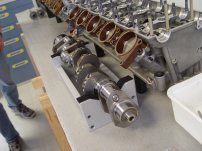
Getting back to the 6 cylinder crank the big worry is effects due to rocking couples which are considerably magnified in an over constrained system like a seven bearing crank. Although a straight six is theoretically intrinsically in balance the actual complementing forces are spread out along the crank. Essentially you have a pair of in-line threes, one at the front and one at the back, rocking about the point where they join. The centre main bearing. All sorts of horrible loading going on once you run faster than the first critical frequency unless proper attention is paid to what's happening. Correctly disposed and sized counterweights significantly reduce the residual forces. Which is why you mustn't take out too much weight as that actually increases the loadings.

Jims R90 BMW racers being a classic example of that. With the big plain bearings front and rear the R90 motor is functionally a pair of overhung crank singles joined by a single web. So the rocking forces want to go through the web. Trimming off the weight to balance it like twin instead of a pair of connected singles was asking for trouble.

Even numbers of cylinders firing at even intervals spread out on a long crank have frequently been somewhat problematic. One reason why the X format aero engines never really worked. The 24 cylinder Rolls Royce Vulture would actually jack the crankcases apart once they'd managed to persuade it not to snap cranks. One master and three slaves as a con-rod arrangement was probably not a good idea either as the extra vibrations are, ahem, "complex". Maybe Napiers had the right idea with the Cub, a 16 cylinder 1,000 hp monstrosity designed in 1919 with upper banks at 52.5° spacing and the other two following at 90° and 127.5° intervals. Which could charitably be described as lopsided. Despite which it worked well enough but no-one in those days really had a use for 1,000 hp in a 3,500 lb package. When it comes to Napier I've always had a sneaking suspicion that the design office had an "all you can smoke" pot of whacky-baccy so they could fill their pipes for free. Hard to argue with the power outputs but the means of getting there tended to "odd" and beyond.

Clive
 
Would it be correct to say that one limiting feature of roller bearings is the different surface speeds of the crank pin OD and the rod ID? Skidding/scuffing must occur on rollers, crank pin and rod surfaces?
 
Would it be correct to say that one limiting feature of roller bearings is the different surface speeds of the crank pin OD and the rod ID? Skidding/scuffing must occur on rollers, crank pin and rod surfaces?
The speed of big end rollers has a continuous cyclic variation as the crank rotates. All good so long as the rollers can keep up with the changes but go fast enough and they fall behind causing the oil film to break down leading to skidding and scuffing. The oil firm is obviously essential but the lubrication severely limits the forces available to accelerate and decelerate the rollers. Dry running ceramic bearings might be interesting but such have their own issues as well as being the other side of the unaffordable horizon.
 
Check out David Vizards "Crankshaft Modification" you tube videos. There are several on lightening, balancing, and streamlining race cranks, and everything this guy does is tested on the Dyno. 35 years ago I worked in a performance shop and we wasted a lot of time learning the hard way what he now posts for all to see for free.
Dave.
 
Clive, nobody can dispute Napiers love of extremely complex designs. *Get a big cheque from the government and go on a design frenzy.
Whilst in the main they did produce some gems such as the Lion, Nomad and the Deltec. One can argue Deltec was a warmed over Junkers design but how majestic it is.


Send the crank to ElectroChrome in Santa Fe Springs (So Cal) They can grind the journal undersize. Build up chrome on the journal and regrind to size.

Last time I was there, there was a Rolls Royce crank that was being ground/chromed/re-ground. and a whole shelf of motorcycle cranks waiting for the same treatment.
 
Bore the PTO stub, main journals and crank throws, you'd have to stop before you hit the oil drill holes.
Does an eight inch contribute to crank strength significantly?
" " Quarter"""""?
.. half, three quarters, one inch?
No.
 
This is definitely going to be a "monkey see - monkey do" make one like the sample job. No way am I going to get clever and try improving something that is known to work. Dave Vizards videos are interesting but I shall stick to what was done even if its clearly not the best when it comes to windage et al.

I've got experience with how weird vibration effects can be and how careful you need to be to avoid resonance. Best story was when I ran a full race BSA DB32 350 cc single as daily transport. It irritated me that the rev counter bracket was a different length to the speedo on so I made a replacement this same length. Looked better and worked fine until on day I decided to verify top end performance on a tempting bit of road. At about 105 mph, averaging out the usual chronometric speedo hop about - maybe - sort of indications, the rev counter briefly turned into a blur and the bracket snapped. So now I knew why short brackets weren't a good idea and got down to copying the full factory set up. Resonances are funny as the only significant difference between speedo and rev counter was the drive cable length. Interesting by sheer luck the handlebars on that bike were just the right length not to vibrate.

Easy to forget that the resonance maths for a crank are basically the same as a transmission line with mismatched impedance's at opposite ends. One end sees a hefty clutch flywheel and transmission. The other just a cam drive, auxiliary drives and, often, a fiddly little bonded rubber and steel disk vibration damper. Up to point the flywheel end is an infinite sink that can dissipitate all the vibration energy it gets sent but the other is close to an open line so energy is easily reflected to rapidly build up if not absorbed. That little bit of rubber works hard. The objective strength of a crank doesn't really matter. Hit a critical frequency and the energy bouncing back and forth will rapidly build up to snap levels if there is nothing to absorb it.

Daves comment about learning tuning stuff the hard way would probably resonate with a guy I was talking to the other day who had raced a Norton Commando for many years. He sent a head off to a certain Mr I.A.M Expert which came back looking the part with big ports, nicely reshaped and polished but was a dismal failure when it came to power output. Basically he spent a pot of money to reduce power by a third from standard. Oops! To add insult to injury the vast amount of welding done to provide material for the work left the head so soft that valve seats and valves wouldn't stay in position. As he said it's always best if you can arrange things so folk aren't learning the job on your money.

Interesting man. One thing I did learn was how important the closing ramp on an inlet cam is when dealing with hemispherical heads. A slower closing ramp actually flows better for longer in the engine as well as giving the valve gear an easier time.

Clive
 
"...would probably resonate with a guy I was talking to the other day..."

Was a funny yes? =)

Story I hear is anyone without a flow bench should never touch a die grinder to a head. Three flavors: 1) looks bad, works bad. 2) looks good, works bad. 3) don't care how it looks, works good. Avoid spending money for (2) above.
 
Might be worth trying to just mill the whole counter weight off and replace it with a smaller more closely situated chunk of tungsten or other heavy metal. Use studs in the crank to secure the chunks of heavy metals.
 

Attachments

  • peugeot6.jpeg
    peugeot6.jpeg
    606.1 KB · Views: 19
David Vizard!

That name brings back memories. I found his engine rebuild manuals the best I have used. I think the first I bought was in the 1970's for Ford 1.6 & 2 litre OHV and OHC engines (Cortina, Pinto maybe) then later Rebuilding Small Block Chevs - an excellent book. Good advise for any similar rebuild.

So good to hear he is still going, will try his U-tube channel.
 
I've set up cranks on rod journals on the mill table then rotated the crank under the milling cutter by hand with a lever arm. Not climb cutting, obviously... My purpose was to obtain clearance between counterweights and piston pin boss for shorter rods than the crank was intended for while removing minimal material. I can vouch for the method.
 
Might be worth trying to just mill the whole counter weight off and replace it with a smaller more closely situated chunk of tungsten or other heavy metal. Use studs in the crank to secure the chunks of heavy metals.
Brett,

That is an interesting crank and cylinder heads. Five big ends - would that be a V10?
 
"...would probably resonate with a guy I was talking to the other day..."

Was a funny yes? =)

Story I hear is anyone without a flow bench should never touch a die grinder to a head. Three flavors: 1) looks bad, works bad. 2) looks good, works bad. 3) don't care how it looks, works good. Avoid spending money for (2) above.
There is much improvement available to folks with common sense and no flow bench. The nicest thing about having a flow bench is you can sell a number, whether you know what you are doing or not. Racers will pay big bucks for big numbers, especially if they can't prove or disprove those numbers. (wet flow, dry flow, horsepower, etc) :D
 
Racers will pay big bucks for big numbers, especially if they can't prove or disprove those numbers. (wet flow, dry flow, horsepower, etc) :D
Depends on the racer. The ones who consistently win pay the guy who does the work, and don't even know the numbers. Or care.

But yeah, there's a lot of guys willing to pay extra to make them feel like their schwantz is bigger. In more fields than just racing ...
 
Depends on the racer. The ones who consistently win pay the guy who does the work, and don't even know the numbers. Or care.

But yeah, there's a lot of guys willing to pay extra to make them feel like their schwantz is bigger. In more fields than just racing ...
+ 10 on that^^^^^^^^^^^^^^^^^^^

Then there's the race dads.
When I worked in the MX shop, we LOVED the race dads.
One day, three crates show up at our dock from Suzuki. 80cc motoX bikes brand new. need assembly.

All three get the "treatment" before they're even run the first time.
One practice bike and two race bikes.

The kids name was Todd Dehoop.

Fucking fearless.
 
Might be worth trying to just mill the whole counter weight off and replace it with a smaller more closely situated chunk of tungsten or other heavy metal. Use studs in the crank to secure the chunks of heavy metals.
Whoo! Thats so far out of my comfort zone that you'd need to borrow the James Webb telescope to see it from there.

This is very much a help a mate out project so the emphasis is on getting it done safely for a reliable crank. Back when I was working for MoD I had a well earned reputation for tying the envelope to the tail of a Lighting F1 and hitting the after burners as simple pushing the envelope was way too tame. But that was the day job and taxpayers money. Better for me to have fun with it before the other folks wasted it.

Concerning flow benches its far to easy to get over-impressed with easily measured steady state flow forgetting that the real flow is intermittent and the true instantaneous port area is set by the gap between valve and seat. Not forgetting the importance of flow inertia in the gas stream and its direction as it moves further into the head and cylinder. Besides getting it in you have to give it somewhere to go. To seriously mangle some Kieth Duckworth comments you have to think like a gas stream and figure out where it would like to go.

Clive
 
Which was why the racing 2 strokes of the 70s (Yam TZ , Kawa etc ) ate cranks, (and they would only stand so many rebuilds before they'd fall to bits and scrap an entire engine)
Most GP two stroke cranks lasted ~300 race miles between rebuilds, 4-5 rebuilds and a new crank was needed due to the press fits in non hardened crank webs getting looser after each pressing. Most people would tack weld on the fourth rebuild to stop them twisting. You could see the heat signatures on the crank pins and rod ends at every rebuild.
Their lack of longevity was entirely due to lack of oil, piston rings would last 100m, pistons 200m.
Contrast that with the four strokes of the time kawasaki z and suzuki gs/gsx which had a lot of racing success, especially in endurance racing and had a reputation for being unbreakable even though they were also a pressed up roller bearing crank. You could put 350hp through a stock suzuki gsx roller bearing crank with carillo rods and it would last a whole season of drag racing.
 
Wish me luck!

Things all went very quiet so was hoping I'd dodged the bullet but the bent sample crank and the one to be operated on arrived late Friday. Apparently the guy who defaulted on the job has now discovered why there is no Disneyfied version of the "Run Over By a Panzer Division Experience".

Took two of us to set-up the bent sample crank in the lathe so I can sort out the template shape and tooling clearance. Bent Crank R.JPGAs it's gash holding in the chuck on the rear flange where the oil seal run is fine. Real thing will get an adapter to bolt it to the between centres catch plate. Catch plate has handy 1.75" Ø hole in the middle so a double diameter plug that will also fit the 1.25" Ø hole in the end of the crank will keep it it all in line.

One of 4 tooling parts to make.

Along with a lifting bar to run between my two chain falls so I can handle the good crank myself. Knew that putting an I beam just beyond each end of the lathe would be handy. Eventually.

Plan A is to remove the cover over the back of the cross slide and fabricate something using the same fixings to accurately carry a template follower to define the curve being machined. Template carrier will slot between the bed shears using the tailstock Vee guideway to ensure accurate location.

I shall make an alloy sleeve to clamp over the main bearing journal to accurately define maxim infeed before starting the cut. I figure it might be better to cut running outwards rather than inwards. Lots of clonk-clonk-clonk interrupted cuts. Which never impresses me. The old P&W B will probably be comfortable at 150 or 230 rpm in low speed direct drive. Wondering if it might be prudent to swop the Dickson QC out for the four way as being more secure.

Need some serious advice on tooling.
Obvious buy all new is to get some round inserts RCMT / RCMK with appropriate right and left holders.

Alternative carbide way is to get left hand holder for the CNMG 12 04 08 inserts I have several boxes of to go with the right hand one I use for general carbide jobs.

HSS way is 3/8" tool bits in right and left J&S holders which will slide down between the webs. Lifetime supply of 3/8 HSS here.

Be a proper "Little & Large" change from the brass M2.9 x 0.6 pitch (!! but 3 mm is too big) knurled head screws I made on the S&B today for an old Erard piano. Hate itty bitty screw cutting. That's what Coventry die heads are for, but when it's a non standard thread in outlandish size what else can you do.

Gotta say its really nice of folk to help out with advice on technique for a new to me job that worries me 'co its learning on another guys expensive parts.

Clive
(planning an early night after watering the veggie plot)


Back
Top