What's new
What's new

How to straighten drill press arbor

Gard

Aluminum
Joined
Mar 18, 2016
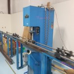
I am restoring a 1940s vintage 20" Walker Turner drill press. The spindle extends about 5 inches from the bottom of the quill. The Chuck and spindle had a visible runout when turned on. The rest of it seemed heavy duty and in decent shape so it followed me home for $200. It was clear part of the problem was the drill arbor so it was removed from the chuck by welding a washer to it and using wedges. The MT2 female spindle taper was nasty and cleaned up on the bench with a finish reamer and tap wrench. A test bar now fits nicely.

The spindle was set on V blocks at the bearing locations and runout was measured along the test bar and spindle, The data is shown in blue. The test bar about 6" from the spindle the indicator was reading +/- 35 mils, (TIR 70 mils) this is about where the tip of a drill bit would be. The TIR decreases to the lower bearing location where the V block is. The area between the 2 bearings is roughly turned and not concentric with the ground bearing locations (no concern here). The spline area above the top of the top bearing is not too bad.
KIMG1163.jpg
Capture1.JPG
Next I built another V block fixture that would support the spindle at the bottom end and top bearing in the 12T hydraulic press. The press applies a load adjacent to the lower bearing location. A 1/10 mil x 1" indicator was used to measure the deflection at the bearing location. The procedure was to slowly apply and remove a "safe" load, record the maximum deflection seen then rotate the unloaded shaft and record the resulting maximum and minimum readings. This is repeated with increasing loads until TIR approaches zero. After each load cycle, the spindle is removed from the press and the TIR at a single point on the test bar is recorded with the shaft on V blocks at the bearing locations. I was thinking it is more important for the test bar to run true than the bottom of the spindle. Sorry about the rotated photo.

KIMG1162.jpg
The next chart shows the measured TIR at the 2 points (2 different fixtures) as the straightening proceeded. As I got closer I was watching the chart with each load to try to predict what the next safe one should be. It looks like I went just a little too far.

Capture2.JPG

Lessons learned. 1st, I bought this double ended test bar because I knew I would need MT3 for a future project, however it is so long that I had to add a weight to the top of the spindle to get it to balance on the V block, should probably of just bought a set of 2 shorter test bars. 2nd, for the first several load cycles the spindle was rotated in the press to find the high spot and then loaded, as I got closer to zero it became less obvious where the high side was and I accidently applied a small load with the spindle at the wrong rotation. I should have clearly labeled the shaft, this side up for load. I have removed this embarrassing and confusing data from the chart.

I also re-plotted the same data as the change in TIR from the initial condition, I think this suggests how much I would need to deflect the spindle to get it better. It also seems to show the bottom part of the spindle may be bent slightly.
Capture4.JPG

That is my attachment limit for this post,
 
The next chart shows an exploded view of the first chart again measuring at several points along the spindle and test bar. It seems like the test bar is sort of parallel to the arbor but offset by 1/2 mil or so. Also the setup for measuring deflection.
KIMG1161.jpg
Capture3.JPG
Walker Turner used custom size bearings so those will cost more than I paid for the press
Looking for any suggestions or comments about what I should do differently or do next.
Reassembling with new bearings it's good enough for an old DP? It surely is way better than when I started...
Another try at straightening to get the test arbor up closer to zero? Is there a better way?
I wonder if a screw driven press would be better than hydraulic for fine control.
At some point would it be better to try remachining the MT2 taper on a lathe? Could this be done with the finish reamer? I am concerned this could screw something up, I guess dialing the upper bearing in at the chuck, steady rest at lower bearing and tap wrench held by hand but centered with spring loaded center in tail stock
 
Last edited:
I have straightened such parts to near zero. My method is to bend opposite to a measured amount.
Best with a straightening press, but can be done with a couple of V blocks and a C clamp.
You tighten down t the floor and then add a little more space .01o can be all the more distance needed...
 
I have straightened such parts to near zero. My method is to bend opposite to a measured amount.
Best with a straightening press, but can be done with a couple of V blocks and a C clamp.
You tighten down t the floor and then add a little more space .01o can be all the more distance needed...

[SUP][/SUP]

Edit
I have corrected my previous post, I had the wrong chart attached, it is supposed to show the spindle TIR at various points along the test bar and spindle. I still have no idea how to change rotation, they are correct when I look at them in my computer.

I know exactly what you mean about the charts, makes sense to me because I made them, not so much to other people.
The left most point on the last chart is the TIR on the MT2 test arbor measured just over 5" from the end of the spindle where the drill chuck will be attached. TIR before straightening at this point was 70 mils, after straightening was 2 mils so I was measuring from +1 mil to -1 mil on the indicator as I rotated the assembly on the V blocks. The end of the spindle was a little worse at about 3 mils TIR. This is the grey point at zero on the X axis.

The blue line on the straightening plots show how far I had to bend the spindle (X axis) and where did it spring back to. The first point on the left is showing that TIR (at the bottom bearing in the press when it was supported at the end of the spindle and the top bearing) started out at 15 mils. The blue furthest to the right shows I had to bend the spindle almost 80 mils (x axis) to get it close to strait after the load was removed, blue point near zero.

It is all muddied up a bit because the charts show data from 2 different measurement, one where the spindle is supported at the MT2 socket and the top bearing, the other where the spindle is supported at the 2 bearing locations. I hope this helps, I am sure it would be a lot more clear if you could see my hands waving around. LOL.

The big C clamp is an excellent idea, I can do that indoors instead of out in the barn where it has been way below freezing for way too long. So what does a straightening press look like? Seems like I would want something where I can control movement to a fraction of a mil so as not to overshoot.
 
Last edited:
So what does a straightening press look like?

The ones I have used were simply a push-down like a screw that you crank, Or a hydraulic ram that pushes down on a part that might be between centers, or to set the part on V blocks or V stands that are movable to better center the error in the part. Often one would indicate the part and mark it. then roll the part on a flat table and mark, then feel the part with the likes of a 123 block to find the exact center of the error/bend and mark again. You would make a decision of where to support the part and where best to push it in a very controlled amount to try and try again so as to not go past straight.,mostly this was for mild /soft parts. To apply pressure in the wrong place, places and you may cause a bend in another area of the part. Bending /straightening solids is much easier than straightening hollow or tube stock.

Hard parts you might do the same exanimation and decide where to hammer wedge to cause stress in the expansion(I forgot the proper stress name for that. Often the wedge was very hard carbide and the hammer was an air-activated device like a miniature jackhammer. you would give a few whacks and test again.
some flat hard part you would bend the opposite way to bump the limiting build-up and almost get to the breaking point and hold there for a time.

I knew guys who would heat with a torch, and let cool, or cool with water but I never got enought experience to do that. Knew one guy who straightened Huge bridge construction I beams with a big torch and buckets of water. It is amazing how crooked I beams can cone fresh from a steel mill.

My buddy Ray's uncle was a ship straightener..He would go with a ship that had a fire and with torch and water would straighten a ship. It was said the crew would think he was crazy and not doing anything...and then the ship would make big sounds and begin to straighten. He would be gone for months on one ship and another going all about the world. Ships bulkheads out of flat and the hatches, doors would not fit or open and close.

Stress in contraction is pulling together, often caused by the rapid cooling of a part that has been burned by grinding..it cools so fast that the surface molecules pull together, often so hard the part is permanently bent well past the burned area.
 
Funny you mentioned bridge repair, I found an old technical report on that and used it to fix a snow plow last summer, I was surprised how it worked. IIRC the cutting edge was about 1/2x6" steel with heavy angle on the back, bent about 1 1/2" over the 8' Not sure I would trust it for more precision work. The report had all kinds of theory of where and what size and shape area to heat, how hot, how much it might move. But still some tryal and error.

Good suggestion on the bearings, it ran OK under power but when I disassembled they were all stiff and crunchy. Someone had previously removed the shielding on one side of each bearing, probably to re-grease. I cleaned them out with solvent but most still do not spin smooth and it looks rusty when I try to shine a light between the balls. It seems like they will not be very well protected from contamination without the shielding. It might be possible to redesign and re-machine it to work with more common bearings but did not seem like it was worth it. There are 4 bearings at around $60 ea so not terrible.
 
Fantastic job straightening the shaft! The plots are very interesting because they show that the bend was at one point on the shaft and you were able to correct it exactly at that point. Your final TIR on the test bar is about 0.001". That's probably better than the drill press was when it came from the factory.
 
Fantastic job straightening the shaft! The plots are very interesting because they show that the bend was at one point on the shaft and you were able to correct it exactly at that point. Your final TIR on the test bar is about 0.001". That's probably better than the drill press was when it came from the factory.

Thanks for that, someplace on Google I found some discussion about straightening shafts and it said the first thing was a survey of the initial condition, measurements recorded at regular points along the shaft as it is rotated. This seemed like it might be a little overkill but I have always like the metrology aspect of machine work. Looking at the first plot and going back and measuring a few more points it was clear the bend was at the lower bearing so I applied the load very close to that point. This seemed like the most likely thing given the damage was most likely caused by a sideways wack on the drill chuck.

Right now the condition is not quite as clear, the high point on the test bar is not at the same rotation as the end of the spindle. Also it it harder to get repeatable measurements with the tenths indicator. I would like to see if I can get it a little closer because I assume it will get a little worse when assembled with bearings. Sometimes I have to remind myself its an old drill press not a modern CNC spindle LOL.
 
Straightening by peening

Sounds like you have this pretty much sorted out. If you need to fine tune it try peening. You can use a cross peen hammer or a carbide tipped engraving tool withn the tip rounede off. Peen the low side of the shaft to add compressive stress. This will lengthen the low side and make it move away from the bend.

Have done tons of straightening with an Eitel press. They work very well. With a shaft like yours that is overhung from the bearing journals the best way we found was to first straighten between centers to get the bearing journal true and in your case also the outside of the shaft at the small end of taper socket. If no center is present in the mouth of the taper you can carefully turn one with a CBN tool. When you are happy with that locate the shaft in v-blocks on the bearing journals and check the far overhang of the socket, or the test bar. It should be close but if you want it closer tweek the shaft.

I had thought about peening or heat straightening but as near as I can tell the bend in the shaft was right where the lower bearing sits and I did not want to mess up that precision surface. I might be able to try this adjacent to the bearing surface. Not sure if I understand the idea. If I put the shaft on V blocks and rotate it to find the high side, shaft is higher in center than at V blocks, If I press down with a high enough force I will straighten the shaft. However if I want to peen, I rotate the shaft 180 degrees so the shaft is low in center, then I do multiple light hits on the shaft and it will automagicially moves up?

I am also not sure working between centers would work, the right side of the shaft that has the splines is 0.75" diameter, the center area is 0.95" and the shorter area on the left (the bottom with the MT2 socket) is 1.2" dia. So if mounted between centers I am afraid the shaft would bend in the center or spline area, not where the bend is. I have to shim up the V block on the right because of the changes in diameter.

The Eitel tool looks very interesting, I have never seen something like that but kind of assumed there was a quicker way than what I was doing. Not sure I understand completely. It looks like there is an indicator set up under the shaft between 2 V blocks (like I have). Then you set a deflection that is relative to the bed or V blocks, then repeatedly hit the shaft to get it strait. The shaft is then rotated and slid along the V blocks to hit other areas as needed. I assume the operator knows or determines in advance what is the correct deflection for a given shaft material, shaft diameter, and V block spacing?

Interesting, if I have this correct, I had not really considered I could keep hitting the same spot at the same deflection and get more movement each time but I guess it seems reasonable. I could put an adjustable jack under the center of hydraulic ram and get a similar effect, might be a little more controllable than the handle on the hydraulic press and watching the indicator.
Capture4.JPG
The blue line in this chart shows the change in indicator height as a function of the maximum deflection it saw in the previous load. So if I want to change TIR by 2 mils perhaps I should set a deflection of 20 mils and hit it several times instead of trying to go right to the predicted 30 mils deflection?
 
Expaining straightening by peening and eitel press

Well I've got to say you really did a good job taking the time to assess the initial problem. Good work!

However if I want to peen, I rotate the shaft 180 degrees so the shaft is low in center, then I do multiple light hits on the shaft and it will automagicially moves up?

Not really automagically. Think of the shaft as a beam located horizontally. The shaft centerline is called the neutral axis(NA). Theoretically if the beam is deflected downward the fibers above the NA get shorter and those below get longer. With enough deflection the shaft become permanently deformed with fibers above NA compressed and those below stretched. By peening the upper portion of the shaft you induce compressive stress that "lengthens" the upper fibers and the shaft moves toward the initial condition.

I am also not sure working between centers would work, the right side of the shaft that has the splines is 0.75" diameter, the center area is 0.95" and the shorter area on the left (the bottom with the MT2 socket) is 1.2" dia. So if mounted between centers I am afraid the shaft would bend in the center or spline area, not where the bend is. I have to shim up the V block on the right because of the changes in diameter.

As a start I would check your shaft between centers. You are trying to put the shaft back as it was when new and it should have been straight between centers. A lot easier and quicker than vblocks to manipulate. Some sleuthing might be required since might be some runout as manufactured. Not saying don't use vblocks at all but centers make sense. This is one spot where the Eitel really shines. Very versatile for shafts of different configurations/diameters. You just have to support judiciously and apply bending force appropriately. There is the option of roller supports for shafts without centers. I finally snagged a press for the money and made the roller supports to straighten bar stock to run high speed in screw machines.

So how does the press work? The press centers are spring loaded so they move down when force is applied and they move back into very precise position when force is released. The operator picks the areas that need to be true and positions indicators on those spots. You can use as many indicators as you want, typically located on areas you want to be true. The indicator assembly includes an adjacent moveable anvil (usually flat not a vblock) that can be postioned or retracted as desired. So you can isolate the straightenng force as needed.The very ends of the shaft are (assumed) true becase they are on the centers. Two anvils are positioned under the shaft and force is applied somewhere between those two anvils, checking with an indicator assembly between the two active anvils. When journal is true you slide the anvil under that now true journal and it stays true as you move to other areas.

The press is controlled stroke. As you apply force the operating lever hits a stop and the press ram ceases downward movement very precisely. The indicator on the journal you wish to be true is set to the high side of the bend. I need to mention the indicator assembly includes an arm that actually contacts the bottom of the shaft so it isn't in the way of the press ram. To set the indicator for example if the bend is .020 TIR set the indicator to +.010 on the dial. Deflect the shaft a bit and the indicator will move a bit as the shaft bends, but only as far as the controlled stroke allows. Release and if you have deflected ths shaft you'll be closer to the zero on the indicator. This is an iterative process and usually more than one hit is required unless you get lucky. There is a cam stop on the operating lever and a knob on top of the lever. As the knob is rotated and the lever operated the ram can move to a lower position. Keep deflecting the shaft and moving the knob until when released the indicator reads zero. That jounal is now straight. And you can move to another position.

There is a learning curve to use the Eitel press but it is really pretty intuitive once you see how it works. We straightend 25" long 9310 carburized transmission shafts within .0015 tir all over. Well at least all the critically functional parts. Anvils were mild steel and the journals hard enough we never had a problem with journal distortion. The mild steel anvils are considered sacrificial and bronze or aluminum can be used for softer shaft materials. Google eitel press ballscrew demo. I met that guy with the beard. His name is Bill Betts I think. Super nice. He is probably retired by now. In practice a lot of times you don't even look at the max straightening deflection but just keep rapidly hitting the part until the properly set indicator reads zero. It looks like this is what Bill Is doing. Unfortunately Eitel has gone the way of mergers and they don't seem as responsive as in days past.

You can use the same pricipals in a manual press and vblocks or flat anvils. Easy to ruin v blocks. Determine where majority of bend is. In your case the lower bearing journal which makes sense. Somebody crashed it and the max bending moment occurred at the lower bearing. Support the business end in a vblock and the opposite bearing journal. Apply force to the lower bearing journal watching a travel indicator set as above. You might have to put the indicator on the top of the shaft. Deflect, release, check if moving to zero, repeat. The difference between Eitel and manual is since no controlled stroke watch the max deflection on the indicator. If the shaft doesn't move deflect it a little more the next time. With patience and it takes a ton you can get very close. Again as a final check roll shaft in both bearing journals and check the outboard business end (or your test bar) and tweak if needed. As you mention with different parts of the shaft being different sizes you have to think about where to place anvils and bending force. You don't have to apply force in the center of the anvils.

Hope this clarifies things a bit and good luck!
 
Other peening examples

I just thought of another couple of peening examples.

Long time ago place made aircraft part about the size of business card maybe .09 thick. Had to be shot blasted. Pass on first size would curl toward the blast like a potato chip. Pass on 2nd side would straighten it back out.

Second one we made a laser housing for space shuttle out of aluminum forging maybe 1'x2'x3'. It was hollowed out on both big faces until a .125 web down the middle was left. Thing weighed 75# when finished so nothing was left. The web started to oil can during machining and a savvy old guy there peened it with a dowel pin. I think there was several iterations of that as the web got thinner. Pretty neat trick.
 
Eitel Press pics

Thought you might like to see a couple of pics of my press. Not center supports but roller supports for straightening shafts with no centers. The two anvils are loose in this case and I just manipulate them as required. The entire shaft rolls underneath the ram on the two carraiges which are connected together with the front and rear tie bars. Doubt I'll ever have to do it but it will accept a 16' bar. When bars are small I have to cut in two or three pcs because the bar sags so much. Haven't figured out how to work around that yet. You can also see the operating lever with knob and dial at top and cam at the bottom.

I coulda bought all the tooling from Eitel but it took them 6 weeks just to quote it and the tooling would cost more than I paid for the press.
 

Attachments

  • eitel 2.jpg
    eitel 2.jpg
    84.1 KB · Views: 47
  • eitel 1.jpg
    eitel 1.jpg
    84.9 KB · Views: 41
Thought you might like to see a couple of pics of my press. Not center supports but roller supports for straightening shafts with no centers. The two anvils are loose in this case and I just manipulate them as required. The entire shaft rolls underneath the ram on the two carraiges which are connected together with the front and rear tie bars. Doubt I'll ever have to do it but it will accept a 16' bar. When bars are small I have to cut in two or three pcs because the bar sags so much. Haven't figured out how to work around that yet. You can also see the operating lever with knob and dial at top and cam at the bottom.

I coulda bought all the tooling from Eitel but it took them 6 weeks just to quote it and the tooling would cost more than I paid for the press.

Thanks for the photos, your description of how the Eitel works is very clear. I was able to see the peening work, moved the shaft by a couple of tenths but it needs more so I brought it back outside to the cold hydraulic press. I have some roughly made V blocks out there so I can monitor progress as it is loaded. Once it warms up in the house I will check it again. My plan is to get the spindle as strait as I can, put it in the lathe and remachine the MT socket a little deeper. I may indicate the lower bearing surface in first, take a skim cut off the OD of the socket area, then put that in the chuck and machine the socket. Sound reasonable?
 
Thanks for the photos, your description of how the Eitel works is very clear.

I may indicate the lower bearing surface in first, take a skim cut off the OD of the socket area, then put that in the chuck and machine the socket. Sound reasonable?

You are very welcome!

If you plan on recutting taper I suggest putting shaft in vblocke on the bearing journals. Indicate the od of the outboard end of the socket. Mark the high spot and record the amount. Remember the indicator cosine error if you are using a test indicator so you compare apples to apples in next step.

Chuck on the journal and indicate it true as close to the chuck as you can get. Move to the outboard end and tap the shaft around until your mark is reading the same runout as in the vblocks. You'll probably have to move back and forth several times to get it right, just don't move the chuck jaws when you are indicating in the outboard end, only tap it. Sometimes if too much jaw contact you can't move the outboard end so chuck on a narrow piece of shim. We always called it a hinge. Maybe you know about this but I'm always surprised at the number of journeyman machinists that don't have a handle on it. Since overhang will be a bunch you might consider using a steady rest. To do so chuck the taper socket up close, indicate your mark in with the jaws and cut a true steady rest journal. The the bearings may not run true back in the spindle hole but if you are careful the error will be slight. Rechuck on journal, check, and install steady rest. You don't want to move the end of the shaft with the steady rest. Consider zeroing a test indicator on the top and the side before making contact with the steady rest jaws.

Hope you have good results!
 
You are very welcome!

If you plan on recutting taper I suggest putting shaft in vblocke on the bearing journals. Indicate the od of the outboard end of the socket. Mark the high spot and record the amount. Remember the indicator cosine error if you are using a test indicator so you compare apples to apples in next step.

Chuck on the journal and indicate it true as close to the chuck as you can get. Move to the outboard end and tap the shaft around until your mark is reading the same runout as in the vblocks. !

That is an excellent idea, thanks. I should of thought of that myself.
What I did (before reading this) was straighten the shaft within about 1/2 mil TIR (WRT the journals), I made a bushing to support the spline end in the headstock bore. If the shaft was longer or headstock shorter this would of been a excuse to build a spider. I chucked and dialed in shaft at lower journal and took a couple thou off the extended end (its about 4" long. Now I have a nice finish on it that I can measure better (it was pretty beat up before). I attempted to straighten out the taper by running a reamer in there supported by a spring loaded center on the tailstock. Not too surprising in hindsight, this did not work very well. When I put the spindle back on journal V blocks, the end is out by 2 mils and the MT2 test bar is out by 3 mils in the opposite direction. So it is way prettier now but still not precision LOL.

I know this may be good enough for a drill press but now it has become an exercise to see how close I can get. I will follow your suggestion next time. The lower journal is 1" dia so I feel like I should be able to get away without a steady rest? This time I intend to set up the taper attachment and take a very light cut with a boring bar. Then the finish pass with the taper reamer will follow the bored hole.

One thing I noticed is that when I measure TIR on the hydraulic press, I got it down to about 2 tenths, then I bring it back in to the V blocks on the journals it is about 2 1/2 times worse. I think this is just due to the geometry of where its being measured and supported. Now at least I have a smooth surface.
 
The lower journal is 1" dia so I feel like I should be able to get away without a steady rest?

You'll have to make the call on that. Practical way to do so chuck it up and tap around on the end and see how easy it moves and make a judgement call.


One thing I noticed is that when I measure TIR on the hydraulic press, I got it down to about 2 tenths, then I bring it back in to the V blocks on the journals it is about 2 1/2 times worse. I think this is just due to the geometry of where its being measured and supported. Now at least I have a smooth surface.

If you're at .0002 TIR BE PROUD! Suspect 2.5 times worse is irrepeatablilty. What brand/style of indicator are you using? Hope it's not a last word.:)
 
You'll have to make the call on that. Practical way to do so chuck it up and tap around on the end and see how easy it moves and make a judgement call.


If you're at .0002 TIR BE PROUD! Suspect 2.5 times worse is irrepeatablilty. What brand/style of indicator are you using? Hope it's not a last word.:)

I have a Digital Mahr MarCator 1087R, .0001 to 1.0 with an arm mounted to the spindle to reach under the shaft. For the V block setup it is a Girod 0.0001 to +/- 0.0055" test indicator, it does not seem as stable.

One thing I notice is the chuck moves by several tenths as I rotate it by hand, pretty sure its in the bearings I am not sure if that is normal, I have an old south bend lathe with bushings and oil lube so there is some clearance in there for oil, between 0.001 and 0.0007".

I am very happy with how it came out, the bottom of the spindle is about 3 tenths when supported by the journals. The test arbor is about 1 mil TIR near the spindle and 3.5 mils at 6 inches away, about where the end of a drill bit would be. This was close to 1/8" when I got the drill. Thanks again for the most excellent suggestions.


Back
Top