What's new
What's new

ID grinding hard chrome.

Terry, check out this Noritake wheel for another possibility. I'd call a distributor and see about getting some more info. It may just be another maker's 5SG.

Also, you mentioned using an "old" single point diamond in this latest post, but I distinctly recall several of us asking you about that in the early stages of this thread... You said you had a new one then. If not, that definitely hurt your process. A heavier dress with a decent feedrate and an at least fairly new diamond are critical.
 

Attachments

  • Vitrified Wheel for Hard Chrome.pdf
    798.4 KB · Views: 1
Terry, check out this Noritake wheel for another possibility. I'd call a distributor and see about getting some more info. It may just be another maker's 5SG.

Also, you mentioned using an "old" single point diamond in this latest post, but I distinctly recall several of us asking you about that in the early stages of this thread... You said you had a new one then. If not, that definitely hurt your process. A heavier dress with a decent feedrate and an at least fairly new diamond are critical.

Thanks, yup saw that, it's Noritake's version of "ceramic alumina" grade. I wrongly stated I was using Norton's 5SG but looking again it's their top of the line 5QN, I found some 20 x 20 mm ID wheels I had to cut down to 1/4" wide from a UK supplier.

I think the diamond was new a year ago when but I ruined it by feeding it straight into the 5SG wheels, Norton recommends a special dresser for them. I added a 15* adapter to my dressing attachment and got the right point and they worked much better after that.

Dresser.JPG
 

Attachments

  • Norton-grain specs.pdf
    3.5 MB · Views: 6
Hmm, that white paper says 5NQ is better suited to low to mid pressure grinding. Chrome is generally pretty high pressure. Did you by chance ever try a 5SG? Or did Norton specifically recommend the 5NQ?
 
Hmm, that white paper says 5NQ is better suited to low to mid pressure grinding. Chrome is generally pretty high pressure.

Maybe that's all he can get with this setup :)

@Terry, is this correct, before I go off half-cocked making stupid suggestions ?

confirm.jpg


And they suggested that the diamond be way off-center at an angle like that ? ID grinders usually (always ?) have the diamond radial to the wheelhead, smack through the middle ... doesn't seem it would dress very clean being all tipped sideways like that.
 
Hmm, that white paper says 5NQ is better suited to low to mid pressure grinding. Chrome is generally pretty high pressure. Did you by chance ever try a 5SG? Or did Norton specifically recommend the 5NQ?

I found another reference that they recommend 5NQ80-JVQN specifically for chrome, I'm using a 5NQ60-KVQN.

Pg 34 here: https://docs.rs-online.com/4f65/0900766b81284f40.pdf

Maybe that's all he can get with this setup :)

@Terry, is this correct, before I go off half-cocked making stupid suggestions ?

View attachment 391376


And they suggested that the diamond be way off-center at an angle like that ? ID grinders usually (always ?) have the diamond radial to the wheelhead, smack through the middle ... doesn't seem it would dress very clean being all tipped sideways like that.

Yup, that's it. I saw different references to locate the point on center or slightly downstream, mine's usually closer to the holder so not as far offset.

Yep, may be. Although he could always grab a beat up 5SG and make a smaller wheel. And I believe your diagram is correct, from what I understand.

I cut some wheels from a 5SG46-KV__ surface grinding wheel and is wasn't good at all, probably too coarse and I left it 1/2" wide but later abandoned the idea when I found the 5SG wheels.
 
Last edited:
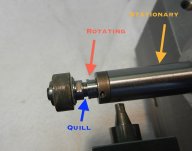
EG asked if blue and orange are rotating and if yellow is stationary in post #124.
I thought the yellow was rotating along with the wheel and quill.
Please clarify.
We would often use a riding steady to ride on a spindle or on a part that would deflect with a 2 or 3 finger push. I will try to find a photo of one on the because I think I sold my last one.
I think a single-point diamond should be at about 15* and following with not pointing toward the wheel center..so that looks OK to me so to be rotated to a fresh facet.
The wheel in post 124 lookes highly glazed or loaded....perhaps too hard.
 

Attachments

  • 1680019306435.png
    1680019306435.png
    958.3 KB · Views: 4
Last edited:
Riding steady.. Plastic or sometimes brass finger would be set to touch or miss .0005 or so from the part or the spindle in the go direction of grinding forces.
Agree you could not use these on your grinder/set-up but I am just showing how they work.. they restrict the part or the spindle from going a certain way/direction so when that space is taken up the set-up becomes ridged/solid..


Last edited:
Buck, Terry can confirm but I believe the yellow is stationary, the bearings are inside of that part.

Correct, also the wheel in post 124 is a CBN resin wheel after truing but before opening up with a dressing stick.

I have a NR-303 spindle coming, it uses a bigger arbor which tells me the spindle and therefore bearings will be bigger also. It's only about 2mm smaller in diameter than my sleeves but I'm hoping to turn the OD down a little for more room, it should be a much more rigid set up.
 

Attachments

  • NSK NR-303.pdf
    1.3 MB · Views: 1
Last edited:
source for various spindles and grinder stuff
 
Not so far mentioned......back and forth with a lathe saddle is cutting two diameters ......because the lathe saddle twists on the bed on the reversal ......dont believe me,try it with a boring bar ......the effect of overcutting on the revrse is well appreciated ,and only a beginner would make that mistake .....yet here we see it.
 
I have a NR-303 spindle coming, it uses a bigger arbor which tells me the spindle and therefore bearings will be bigger also. It's only about 2mm smaller in diameter than my sleeves but I'm hoping to turn the OD down a little for more room, it should be a much more rigid set up.

Does the stationary spindle (marked yellow) go into the hole ? A little bit or a lot ?

About the quill, I'm jumping the gun here but my plan would be to make one yourself along the lines of the Big40 toolholders or whatever they call them, fits against both the taper and the face of the spindle. Will be a bit of a bitch to make but should give a measurable amount more rigidity.

May as well reveal all while I'm here ... you've got the thing to kind of grind so at least you know it's possible, now worth it to work on incremental improvements ?

Your skinny spindle thingy hangs way out, while the motor is captured in the travelling slide ? I'd make new mounts that move the whole thing back, hold the spindle right out next to its nose and let the motor hang out the back in space. That long thingy is just a tuning fork, the closer you can capture it to the grinding wheel the better. I bet it's singing a pretty song there while you grind, especially with those bearings inside whirling around.

If the stationary portion is only going in a little ways, then I'd probably actually move it back a little, capture it in the slide as close to the bearings as you can in as beefy a clamp as will fit, cast iron not aluminum, and make the quill a tad longer to reach farther down the hole, but as big as you can. It seems like you'd gain more that way than lose, those bearings spinning around are making bad bad bad, bad vibrations and the tuning fork aspect of the setup magnifies it.

And one more thing that might help even a little but would be fun to do at least : on a heald, the table weighs I dunno, about a thousand pounds ? Yours is lighter :) but you could probably pull it out, counterbore a grid of 1" diameter recesses, then pour lead into those. Lead is good at damping and the weight plus the vibrations-absorbing might help. Or use carbide, but can't melt and pour that, not as much fun. A little more mass, a little more damping, can't hurt. Might even take fifteen minutes per off the grind time, and I know you'd rather mess with this than just get a little Bryant :D
 
Last edited:
Actually ... at this point you are so far down the road, it would almost be practical to take your recip grinder thing and build a table with a cross-slide (not linear bearings !) and mount a spindle on one end for the workhead. Those are not very expensive. You could enclose it for flood coolant and save wear and tear on your nice lathe, it'd mostly be a welding project with one or two tricky spots, wouldn't take up much space but in the end ... you could even automate it - the Keeley Cylinder Grinder :)
 
Ya, that dinky little 13mm end of the spindle goes down the hole, the sleeves are about 1.7" (43mm) long. Now that I've gone over everything with a tenths indicator and tightened it all up I think that's where I'm losing rigidity, plus the fact it's a 400 lb. lathe and not a one ton grinder.

I thought about making a spindle but hoping this new one will work, the sleeves are 24.6mm I/D and the new spindle is 22.8 O/D. I'm hoping to turn it down a bit for a little more room as it won't take much dressing and the wheel will be trash. Hopefully they use 16mm O/D 688 bearings and not 19mm 607's.

The first attachment is the spindle I have followed by the one I'm getting and the air motor they attach to.

AMH-301.jpgNR-303.jpgAM-300R.jpg
 
Last edited:
I thought about making a spindle but hoping this new one will work, the sleeves are 24.6mm I/D and the new spindle is 22.8 O/D.

Which means your wheel is going to be like 23mm dia for a 25 mm dia bore ? That's a whole heck of a lot of contact there :(

I must be missing something cuz pretty sure that wouldn't work very well ...
 
1680174519769.png

I typically don't like steel on steel facing in a wheel mount assembly. If so the fit of the first spacer should be .0002 (slight feel fit) or so Id to Od fit to the arbor/quill stub and I would likely also have a blotter there, between steel on steel faces...and for the best assembly the wheel first blotter would be against the quill face, not such a spacer..Likely a new quill would need to be made. IMHO.
* Perhaps blue Loctite would assemble the first spacer solidly for the existing wheel assembly and 250* heat could remove it if necessary (red release is about 500*).
Agree this is likely not all of the problems, just one factor that I don't like.

I agree with EG in post #137 if a 23mm wheel would be used for a 25 mm bore. .
 
Last edited:
If you push-pull on the Russian's wheel spindle you are push-pulling on 60 pounds of weight...that is a lot of rigidity, and it's bolted down so more.
If you push pull on your wheel spindle how much (watching an indicator) deflection do you get with 3 fingers (about 30 pounds of push pressure)?
With the wheel-mount steel on steel corrected and perhaps 2 steadies opposite the go direction your setup might be more rigid.
With a steady set .001 away the wheel spindle setup goes .001 and then becomes solid...It could be set at zero. Vespel and nylon are OK if a plastic steady is used.
The Go-directions may be to/towards push away and lift the part.
I know, how do we know the Russians are doing any better than you..but it seems you are spending a lot of time in the grind.?
 
Last edited:


Back
Top