What's new
What's new

Incorrect control voltage to VFD, 5 hp CNC mill

M. Moore

Titanium
Joined
Jun 8, 2007
Location
Vancouver Island, B.C. Canada
As the title suggests I am having a problem with an incorrect voltage to the VFD on my vertical CNC mill. I thought it was a torque problem and posted about that twice and now after much research and testing I have narrowed the problem down to the voltage signal that controls the motor rpm. It is an Anilam 3000 control that was an upgrade from the 1000 series in about 2010. (previous owner)

The VFD uses 5 volt or less input to alter the spindle speed. I don’t know the exact range but it is something like 3-5 volts. After a call to the very helpful tech from HHRoberts (Topwell mill) I used a 3 volt transformer to apply power (actual was 4.2v) to the VFD (Baldor15H) and then turned on the spindle via the machine control. It worked fine and the spindle was smooth and steady at around 1700rpm.

So that tells me the VFD is working fine and I had already tested the VFD by using the keypad and starting the spindle, which worked perfectly.

So I re-installed the leads from the control to the VFD and tried again, no good as the spindle sounded terrible and when I checked the voltage it was over 12 volts. Not good at all. This was a new development as previously it had been working but pulsing up and down and would not go lower than 2000 rpm.
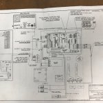
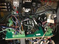
I checked the power supply voltage and it was spot on at 5 volts as it entered the system board. Then I checked the wires leaving the breakout board and it was 12+ volts.
So can anyone shed some light on what is happening on this system board that is causing the 5 volts to increase to 12 and or why it might have happened? Old age?

I tested the output of the leads to the VFD by attaching my meter and then choosing a speed on the control, it showed over 12 volts and did not change much when I used the spindle speed control knob to go down in 10% increments. Leads were not connected to the VFD for these tests.

This whole odyssey started when the end mill I was using slowed down in the cut like it was losing torque. Any help will be much appreciated.

Michael
 
Makes me wonder if the control is sending a pulse to the vfd that is averaged with a capacitor and resistor to make a variable DC voltage. If those components fail then you may be reading the peak voltage, which is 12 volts.

You might consider buying a cheap 50$ digital oscope if you don't want to spend 100 to 200$ on a good used one.
 
Johansen,
Thanks for your reply. I just talked to an anilam expert who sells parts and based on my testing the problem is in the motion control board inside the machine control, right behind the screen. The board can be repaired but needs to be sent to the US and back so downtime will be a problem.
New board is $2500 by the time I get it here.
 
Hopefully the new board is on its way and I have temporarily connected a transformer to the VFD with a variac to control the voltage. Works like a charm but I have to manually adjust the speed when changing tools. The control will still turn on and off the spindle as that is a separate circuit to the VFD.
I have learned a lot about how a CNC works instead of learning how to make it work.
 
Update,
The new board arrived and I successfully installed it into the control console. I then did all the steps necessary to get it up and running again. I had to balance the servo motors and did that successfully with one minor issue but that is for another post.

Once everything was working well with the control I tried to start the spindle and it spun up to speed but had the pulsing sound again. I then checked the control output voltage to the VFD and it was 6.8 vdc. I had set the speed to 2000 rpm which is 50% of maximum so the output should be almost exactly 5 volts. ( I now know that the control voltage to vfd is 0 to 10 volts)
The control is sending 5 volts to the vfd as measured with the leads disconnected but as soon as I connect them and turn on the spindle the voltage increases.

So I have learned a lot about how this machine runs and now I am baffled as to why the voltage is increasing when running the spindle. When I asked Jerry Bouvier if the motion board died because of this extra voltage he replied that it was a very possible outcome but he thought it was coming from a bad vfd. So I have been reluctant to test the spindle again given that the board cost over $2500 dollars. ( bought from Jerry who has been immensely helpful)

I connected an external control power source to the vfd so I can run the machine and I have now run several small jobs with no problems. I used a nine volt small transformer (desktop calculator?) and connected it to my very old variac so I can adjust the spindle speed. This works well other than the walk back and forth to adjust the speed as needed. The control does turn on and off the spindle which is a nice feature. The vfd performs perfectly with the external power source, no pulse or torque issues. Strong steady speed and it sounds perfect.

The vfd will run the spindle from its control pad and it works perfectly as well but then I don't have on/off control from the console so my variac hack setup works better.
So now I have spent a lot of time and money and the machine is performing only a little better than before I swapped out the board. I did test the output from the control again today and at 2000 rpm the voltage was reading 5.6 and it was pulsing.

Ok, now that you have read all that, how is the voltage increasing from the control when I start the spindle? It is not feedback from the vfd as that would happen with my hack setup and it does not happen. So my simple logic says it has to be the electronics in the control. Jerry thinks it is the vfd but I think it is in the control electronics but I have no way to figure out the problem as I am not at all good with electronics but I can do testing and have some understanding of simple circuitry provided I have some guidance on where to look/what to test.

I am now stuck and don't want to risk ruining the new board unless I can test it without it feeding bad voltage back to the board. Also the original problem was not exactly the same as what is happening now but it is similar. It is also possible that with all my rummaging around in the control cabinets I have made the problem worse in some way. This would be par for the course in respect to the things that happen to me in regards to machine repairs over the last 30 years.
 
wag
your neutral logic power to vfd is different from neutral power to board. the voltage is then different with the intended positive from board to real voltage at the vfd.
 
Check the actual output across the terminals on the control source (the control board). It may be correct, and there may be some voltage extra that is appearing between the control source common wire and the common at the VFD.

That can come from many causes, the first thing is to see if the control source has the right voltage across its actual output.

If so, then there is extra voltage creeping in.

If not, then the extra voltage is coming in due to the connection, and there may be current flow (that should not be present) through the common of the control board when the connection is made. That is not good, as it can cause damage.
 
It is a guess on my part and it makes logic. The vref ground or negative has to be at parity with board or bob out signal or the vfd is reading a contaminated signal. The vref ground is not the same as machine ground (big fat green/yellow wires going to everything then the wall). Vref is the negative of your logic dc (board rpm signal and out from your on off forward reverse relays).

I think you said earlier it sounded rougher at higher rpm- that could be noise from vfd also. There is a rabbit hole of wiring voodoo. Shielded cable shielded going left to right or right to left on your radio dial - or both. Guru did a good discussion on it with when to shield both ends or one end. Which end is voodoo.
 
JST,
I think I can do those tests but need some help in respect to doing the right tests. The motion board is inside the console and there is not much access. I also don’t know where on the board to test that output voltage.
Is it possible that the spindle forward/reverse control wires that go to the vfd have any connection to this problem? When I first was checking things the white wire on the f/r had slipped out and so I put it back where I thought it was supposed to go. There are only two choices but the two choices appear to be jumpered together so I tried both and they both work. I have the manual for the vfd but could not determine which location was correct. I can post pics of the vfd control wire terminal strip and the info from the manual if it will help. I have not tried the other terminal with the new board in place for the rogue white wire.

mjed,
The spindle has a pulse sound but it doesn’t sound rough, it sounds like it is going slightly up and down in rpm but when checked with my tach it seems steady.
At this point I have only run the spindle briefly as a precaution with it connected to the new board.
 
The place to check is where the wires that go to the VFD end up on the control board. I understand that they go through a breakout board, and may be hard to trace back.

You should have an Anilam manual, which will give the correct connections at their end, and allow you to determine if the correct voltage is coming out if it.

The breakout board is another question. How things get interconnected on it is a question. Depending on how wiring is handled (is the common commoned, or each separate, for instance) it could cause an issue.

As for the VFD, what type is it? If we can locate a manual, it should be easy to determine the correct connection.

Yes, pics are good.
 
Here are some photos.
The vfd chart is one of four options and I think it is the correct one but not 100% sure. It is a Baldor 15 series vfd.

The control was upgraded from the 1100 version to the 3000m version and these schematics were in the user manual. The upgrade was done by the previous owner. The info in them is not exactly what is in the cabinet but it is close.

The #1 and #2 control wires to the vfd are the input for spindle speed. The two wires shown are my external transformer. Wires 9,10 and 17 are the spindle reverse wires. You can see all the jumpers as well.

The white wire came loose after I opened the cabinet and just touched the wiring to move it down so I could see the numbers on the terminals. Someone had put tape on the wires with the terminal number but the white one was faded too much to read. I forget what 18 and 22 are for but could trace them again. There was another control wire connected to the terminal block that went up to the motor, it was not connected to anything in the motor so I took the wires out of the terminal strip and tucked them behind.
 

Attachments

  • CNC1.jpg
    CNC1.jpg
    107.9 KB · Views: 5
  • CNC2.jpg
    CNC2.jpg
    92.9 KB · Views: 5
  • CNC3.jpg
    CNC3.jpg
    60.7 KB · Views: 7
  • CNC4.jpg
    CNC4.jpg
    59.8 KB · Views: 9
  • CNC5.jpg
    CNC5.jpg
    133.1 KB · Views: 7
It is beyond my pay grade to see control wires to what where.

Vfd input #17 should be the only negative (vref) dc wire from the board to vfd. If any command has a two wire connection something is miss wired. This point should show exactly zero volts if checked against the control boards negative power supply. If you check this same point to machine ground you might read noise voltage depending on your meter.

All signal wires are positive leads, except the one going to #17.
 
memphis,
I don't quite follow your statement about the two wire connection? The next page of the vfd manual shows a two wire layout, maybe that is the right setup or the way mine is done?
There are only two wires from the motion board terminal speed control circuit to the vfd, if I check them on my meter and then reverse the test leads I get a positive or negative reading, I assume that means one wire is positive dc volts and one is negative? Or are you talking about just the forward reverse wires?
I may be misunderstanding how the vfd works but aren't those wires just normally open or normally closed? The forward/reverse command from the control closes a contactor inside the cabinet which tells the vfd which way to turn the spindle? No voltage needed through the signal wires therefore not positive or negative? Or have I got it all wrong?

I should have time tomorrow to test the motion board output as I would like to do that to find out where the extra voltage is coming from as you detailed earlier.
The voltage from the motion board measured at the breakout board is exactly five volts which is as it should be when the speed is set at 50%. That measurement was done without the wires connected to the vfd, once connected the voltage changed.
I am unsure how that can happen unless there is a fault in the vfd or some feedback from the other control wires connected to the vfd.

In the last photo you can see the two wire connection point of the speed control out of the motion board in the green terminal. It is on the right middle area with a masking tape label. I doubled up another wire so I could connect the meter easily. Below and to the left is the long black connector that has many wires from the console to the breakout board. Miracle of miracles some of those wires are actually labeled but I did not have time yet to find the speed control wires.
The power source module is just below the breakout board. To help me understand how this works would power go to the motion board and then back to the breakout board at the required voltage for the speed selected?
Sorry for all the dumb questions but electronics and electrical work in general is not my strong suit.
 
Well, I see that 1 and 2 are the analog ground and the control input for a potentiometer.

But, the correct analog inputs for this sort of purpose are 4 and 5, which allow connecting two wires and should, per what I see, isolate ground so that there will be no interference. It appears to be a "differential" input, which cancels reasonable amounts of "common mode" noise that may be due to different grounds.

You would have to program the unit parameters to respond to those inputs, presumably using the 0 to 10 volt range.

That input set will respond to a variety of input types, including a 0-10 volt type, and is the input intended to respond correctly to the sort of control voltage you have.


Back
Top