Peter S
Diamond
- Joined
- May 6, 2002
- Location
- Auckland, New Zealand
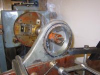
I have just bought one of these little machines and wondered if Tyrone, PDW and any others familiar with them can give me any tips for moving it, please?
For example - does the counterweight need to be removed or chocked?
Were there any special tools that I should be looking out for e.g. hook wrenches or ?
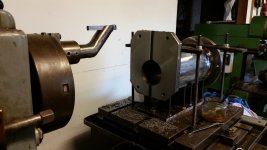
I haven't seen it yet, so I can't tell you much about it, except it is the Facing Chuck model (not the Collet Model), with the boring stay and has a rotating table.
I have a Kearns brochure which says it would have been supplied with bar holder, facing tool holder and 3MT drill socket (1&2 MT sockets optional).
Boring bars were "Additional Equipment", 1", 1 1/4" & 1 1/2" each with a bush for the boring stay.
Any advise, comments etc. welcomed, thanks!")
I think this brochure is pretty old, perhaps 1949 going by the code on the back cover. I daresay there are 'Kearns' machines in all of the countries listed below:


For example - does the counterweight need to be removed or chocked?
Were there any special tools that I should be looking out for e.g. hook wrenches or ?
I haven't seen it yet, so I can't tell you much about it, except it is the Facing Chuck model (not the Collet Model), with the boring stay and has a rotating table.
I have a Kearns brochure which says it would have been supplied with bar holder, facing tool holder and 3MT drill socket (1&2 MT sockets optional).
Boring bars were "Additional Equipment", 1", 1 1/4" & 1 1/2" each with a bush for the boring stay.
Any advise, comments etc. welcomed, thanks!
I think this brochure is pretty old, perhaps 1949 going by the code on the back cover. I daresay there are 'Kearns' machines in all of the countries listed below:
Last edited: