What's new
What's new

KO Lee S618 Grinder Disassembly

Arnox

Plastic
Joined
Oct 19, 2022
Location
Elizabeth Colorado
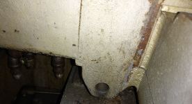
Hello, I'm new to this Forum. I purchased a KO Lee S618 Grinder and have started to disassemble it. Much of it is strait forward, but I'm not able to loosen the control knobs and handles on top of the saddle. Haven't found any info on this and don't want to wreck or mar them up. I do have the Allen screws loose, but that's it. Any help on this would be much appreciated. Thx Steve20221019_171043-sml.jpg
 
Can't help you much on your model of the surface grinder. Mine was the Tool & Cutter grinder. I found the handles to be a snug to tight fit to the shafts. Remove the set screws completely and make sure there Isn't another stuffed in there. Also make sure they didn't install tapered pins in the handles along with the set screws too. Once that is done get you a small bearing puller that can squeeze under the handle slightly and press on the shaft to remove. I'm afraid if you start prying on the handle you may mess up the shaft going into the hydraulic valves. That happens, you'r screwed. Just go easy and I bet they will come out with ease. A little penetrating oil may help too. Ken
 
I also would not pry upwards on the handles. Use the puller if you need to, but as Ken said, first fully remove the setscrews and investigate under them to ensure that they aren't doubled up nor dog point. If they are dog point and only slightly loose that can hang you up too.

The front handles on my Brown & Sharpe grinder were held on by a nut under a cover but they were also a tap fit; I used a puller with no issues. Yours may be similar, or just tight from a little corrosion and/or gunk packed in over the years.

Looking at the parts list from a sightly newer 618 grinder, it appears that they are just a setscrew tightened against a flatted shaft.

20221020_105548.jpg
 
Last edited:
You may also consider the need to tear it down / error dissembley and break something is not uncommon. Use labeled ziplock bags sharpie marked for all small parts.
It looks like a 3/8 x 1 1/4 cap screw goes up through a plate to catch to cross-feed nut (?) .
Agree most set screw assemblies may have a piggyback (2nd) set screw and can be puller pulled, torch heat up can be good / but you don't want to cherry-hot heat things.
For one thing, a little cross-feed play is common and is dealt with even on an almost-new machine.

Looks like the schematic I gave is for before 1949, you can magnify it with your computer.
 
Last edited:
Thanks for your replies and tips. I was able to get levers and knobs off by heating them up a bit. Hope this didn't wreck the shaft seals... There's only the set screws holding everything on, however the knobs have a set screw under the lower ring which needs to raised up to access it (see pic). These haven't been off ever probably and were pretty gummed up and stuck on...

20221020_105116-sml2.jpg
 
Last edited:
Good to list any disassembly info /photos to make this thread an asset to other Kolee owners. "Great Photos."
Buck

Ops... looks like your location is a mystery.
If you remove the chuck put it back on with an elbow swing arm twist /not a pull from your shoulder..or less than about 20lbs.
 
Last edited:
Here's a review on the hydraulic actuator valves. All but the table reverse valve have a bar bolted across that have 3 Allen set screws which press down on the valve retaining plate (basically a big washer) to adjust fitment and turning resistance. Normally the valves can be pulled straight up and out by grabbing the stem. I had 3 of them that wouldn't turn and were stuck. Used a punch and hammer to gently hit the retainer down (also penetrating fluid), moving punch around and around until the assembly moved which means it can be pulled up and out. There's two O-rings, an outer one that seals against the case and inner one that seals the shaft. If removing the retaining plate up off the shaft make sure to first debur the shaft. Here's a pic of valves all cleaned up and the last one ready to go in...

20221022_150840-sml.jpg
 
I spent a bit of time figuring out how to remove the table and what needed to come off to accomplish this. Turns out its not as easy as a lift off or slide forward. There's the typical things to disconnect/remove, the pressure supply and return lines along with the four way retainers which are located on each corner underneath, two in front and two in back. The Y-axis crank shaft support keeps the saddle from sliding off forward (1st pic below). And the Y-axis locking mechanism located between the cylinder and the way, keeps the saddle from lifting straight up and off (2nd pic below). The locking mechanism has two flathead Allens that hold it to the underside of the saddle. I didn't have anything to get them out, without first removing the cylinder, which is held on with four Allen screws. The screws that hold both of these to the saddle are very difficult to remove. I'm sure the factory had a much better way to do this, and its possible the pin could have been driven out with a punch, but I didn't know if it was just a press fit at the time. Once they're all out the table will lift straight up... Another thought is that the saddle possibly could have been lifted up a bit and shifted to the left so the L-shaped lock plate would clear the way.

Saddle Y-Axis Crank Shaft Support - sml.png
Y-Axis Hydraulic Cylinder & Locking Mechanism - sml.png
 
Last edited:
Here's the saddle off and cleaned up. The X-axis cylinder is removed for cleaning. Turns out there's no oiling running to the Y-axis ways. However, they do have oil reservoirs and wheel oilers, but need to be manually oiled via the tubes sticking up in the oil tray, the left one is right next to the red capped oil line. And yes, the table needs to be removed. The only thing that needs to be removed is the hydraulic cylinder shaft nut on the table right side and it can be lifted straight up and off.

Saddle Removed and Cleaned Up -sml.jpg
 
I fill my Y axis oil reservoirs without removing the table. I wish I still had my old railroad-type oil can with a long horizontal tube, but I don't. I cobbled up a small funnel attached to a piece of bent copper tube. If I move the table all the way to one end I can stick the tube into the top of the hole and then pour oil into the funnel and fill it that way, repeat at the other end. Only way I know how to know when they're full is when oil starts seeping out below the saddle.

metalmagpie
Good to know, I'll have to rig something up...
 
Travel has to do with the position of the travels to the spindle and in the world, some surface grinder manufacturers call the travels differently.


* Any photos of the long travel table-holding devices/removal could be helpful to other Kolee owners.

Any addition/design change that you can improve to keep grit from entering from the column side of the log travel should be considered, such as a felt strip or a strip of masking tape.

Do you have a proper wheel for grinding the chuck?
 
Last edited:
Travel has to do with the position of the travels to the spindle and in the world, some surface grinder manufacturers call the travels differently.


* Any photos of the long travel table-holding devices/removal could be helpful to other Kolee owners.

Any addition/design change that you can improve to keep grit from entering from the column side of the log travel should be considered, such as a felt strip or a strip of masking tape.

Do you have a proper wheel for grinding the chuck?
I do not, once I have machine together was planning on getting one. Suggestions are welcome. Don't quite understand what you're referencing above (i.e. travel table-holding devices/removal). The travel table actually isn't held on the saddle at all, it just rests in the ways and is connected to the hydraulic cylinder on one end. And I'll need to think about what can be done on the column side long travel way to keep grit out...
 
The things you mentioned to remove the long travel section, could be photoed so other will know how/what to remove.
The chuck top surface finish is not as important as absolutely cool grinding.
often a 30-36-and 46 open grit wheel will be used (perhaps a 54) for chuck grinding.
I am an experienced grinder hand so I use a 46I very open wheel. Chucks can be ground dry, but doing so is a huge chance of heat swelling and burning the chuck. Wet is best even if using a hand spray bottle.
Many guys burn the first chuck grinding by letting it get hot to swell up and suck into the wheel.
best to grind with very small down feeds, frequent sprays, over-travel at the off ends, pause and rest, feeling the chuck for warmth. I use small cross-feeds. lately, I see guys making big cross-feeds perhaps Ok but I think that is taking a chance to burn a chuck. I have groungd chucks that had a .015 low area..a real bugger t grind...Over-tightened chucks can actually bend the top table losing the flatness of the bed way contact.
Here is a good chuck-grinding video.
 
Last edited:


Back
Top