What's new
What's new

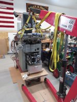
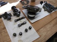
KO Lee S618 Grinder Disassembly

Richard King may suggest that you flake broad flat areas of ways..I hope he notices this thread and gives advice.

Likey if he had it that far apart he would re-scrape it to like new....and with that, it would be better than most new SGs on the market today.
 
Last edited:
The things you mentioned to remove the long travel section, could be photoed so other will know how/what to remove.
The chuck top surface finish is not as important as absolutely cool grinding.
often a 30-36-and 46 open grit wheel will be used (perhaps a 54) for chuck grinding.
I am an experienced grinder hand so I use a 46I very open wheel. Chucks can be ground dry, but doing so is a huge chance of heat swelling and burning the chuck. Wet is best even if using a hand spray bottle.
Many guys burn the first chuck grinding by letting it get hot to swell up and suck into the wheel.
best to grind with very small down feeds, frequent sprays, over-travel at the off ends, pause and rest, feeling the chuck for warmth. I use small cross-feeds. lately, I see guys making big cross-feeds perhaps Ok but I think that is taking a chance to burn a chuck. I have groungd chucks that had a .015 low area..a real bugger t grind...Over-tightened chucks can actually bend the top table losing the flatness of the bed way contact.
Here is a good chuck-grinding video.
Good info and tips! Thanks...
 
Making progress on all the things needed to purchase and do in order to be ready for re-assembly. Currently welding up holes in the hydraulic tank. Have new pressure / return hoses. Need to buy hydraulic oil, looking in the instruction and parts list book there's a page of oil cross references, but this is ancient. Looking for recommendations...
 
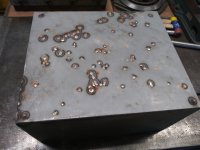
Well its been quite a while since my last post. This has been a "time available project", but I have made quite a lot of progress and have a lot of posting to do. One part that took some time was repairing all the holes in the hydraulic oil tank (coolant tank is even worse). Also just getting it cleaned up to weld on was a lot of work! Here's pic of bottom all patched up.Oil Tank Bottom - sml.jpg
 
I came up with a modification so the saddle ways can be oiled. I formed a 5/16" brake line which fits real nice into the existing tube in the table. This tube needs to be cut down, as its a bit of a tight fit due to clearance issues with the underside of the table. Here's couple of pics...Saddle Way Oil Tube 1 - sml.jpgSaddle Way Oil Tube 2 - sml.jpg
 
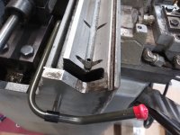
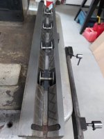
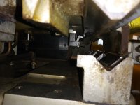
I tried to figure out if its possible to set the saddle onto the base with the crossfeed locking mechanism installed. Thought the saddle could be tilted a bit and held to the left side of the way 'V' a bit thus allowing the clearance needed. And as the saddle gets lowered and the locking mechanism clears the inside lip, then move the saddle right and onto the way. Turns out this just can not be done! So the install operation is the reverse of the removal, which is very tedious and frustrating. Here's a couple of pics that show the issue. Its difficult to get good shots of this, probably the 2nd photo shows the issue better. As can be seen the way has an inside lip that the locking mechanism fits around. When in place the locking mechanism, which is a 'C' shape fits around the way inside lip. Once this is done, the crossfeed cylinder needs to be installed. Stay tuned...

Saddle Way Lock Mechanism - sml.jpgSaddle Way Lock Mechanism 2 - sml.jpg
 
I decided to do the test run and not install the crossfeed cylinder where it goes, under the saddle. To fill the oil tank takes 5 gallons, actually a bit more. Fired up pump, no leaks, wow! Table cylinder worked great! Crossfeed cylinder only moves inwards and control valves have a bit of oil working up and out. Don't know what's wrong here, but after some thinking and testing decided to remove and take apart the crossfeed valve body. There are two plungers/pistons in it and one of them is stuck solid! Working on getting it freed up now...

Almost Ready for Test Run - sml.jpg
 
Hey Buck, what is small to you for stepover on grinding a chuck and could you list a part # for Radiac or Norton (if that's what you use) on the 46I. Thanks!
 
Got the stuck piston in the Crossfeed valve body loose and cleaned up/out all parts. Put back in, fired up and it works! But my earlier no leaks statement was premature, as now have leaks in multiple valve stems. Need to buy O-rings for all valves and shafts I guess. Will try contacting the company that bought KO Lee, LeBlond Ltd. Does anyone know of a source for them?

Crossfeed Valve Body Apart - sml.jpg
 
Was able to get an O-ring and gasket kit for the valve bodies from LeBlond Ltd. although it was expensive! This fixed all the leaks, so I guess it was worth it. Here's a couple of photos, first are the valve shaft and base O-rings, and second is the long feed valve body apart. It has four layers with a gasket in between each, two are the same and the third is different. The kit comes wrong, the two and one gasket combo needs to be the other way. I called LeBlond and they sent me the second right gasket, no charge.

Valve O-Rings sml.jpg
All Gaskets - sml.jpg
 
Last edited:
Put table back on. Here's photo of bottom and one sliding it onto saddle. As can be seen there's nothing holding it on, only the insert for the cylinder rod to attach to.

Table Bottom 1 sml.jpg
Putting Table On 2 sml.jpg
 
Also its important to adjust the three set screws on the retaining plate so the valve is positioned all the way down into its well. Otherwise there will be fluid flow under the valve that shouldn't be. Best way to do this is to back off all three set screws and bolt retaining plate down. Then turn each screw a little bit at a time and continuing this around until the valve stops turning then back off a bit on that screw. Turn the remaining two in a bit until another causes the valve to stop turning and back it off a bit. Finish up doing same thing with last screw. This also determines the turning resistance level of the valve. Resistance will be increased some when pump is running. Really can only set this by trial and error, so to speak. Its also personnel preference as well.

Untitled.png
 
How big a wheel will fit your wheel guard?
I might have a wheel for the chuck grind that I could post to you.
Be sure not to over-tighten the chuck hold downs 20 lbs is plenty.
And be sure the wheel travels over the chuck wide ways.
QT: (need to buy O-rings) automotive shops may have a wide selection.
Will take up to 8" diameter and my adapters 1/2" to 3/4". I tried some automotive O-rings in the cross feed reverser which didn't work out. Need just the right diameter OD, ID and thickness is important too. Getting all the various different ones seemed to be near impossible... In addition, getting valve bodies apart without tearing the gaskets is "iffy" and the original ones are very thin and brittle with age.
 
I don't know if I mentioned this..put a triple layer of masking tape at the open space at the moving long table to the saddle at the lower edge/to cover the opening... with the lower/saddle oiled so the tape only sticks to the moving long table. Paint it like your machine and it makes a pretty durable grit stopper. Grits bounce off the collum and get into the ways. just overlapping about 1/4 " is Ok... likely 1" tape for most grinders. try to not spray paint into the ways.
I usually just straight-edge test the set pad and chuck bottom for flatness and install the chuck. Not uncommon to grind the set pad and the chuck bottom that is up to you.
 
Last edited:
Here's the saddle off and cleaned up. The X-axis cylinder is removed for cleaning. Turns out there's no oiling running to the Y-axis ways. However, they do have oil reservoirs and wheel oilers, but need to be manually oiled via the tubes sticking up in the oil tray, the left one is right next to the red capped oil line. And yes, the table needs to be removed. The only thing that needs to be removed is the hydraulic cylinder shaft nut on the table right side and it can be lifted straight up and off.

View attachment 378317
I recently disassembled my S618 and there were wicks in those tubes, is that correct?


Back
Top