What's new
What's new

Machining intersecting radii/cylinder

Fal Grunt

Titanium
Joined
Aug 5, 2010
Location
Medina OH
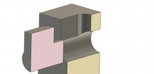
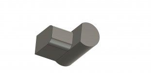
I have a part that I am trying to figure out how to machine that has an intersecting radius and diameter perpendicular to each other. Radii? Cylinder? Look at the picture and it'll make sense.

I initially looked at casting the parts, because they are small, and to me it is a great part to cast, but all the quotes I got back were $6-$8k for tooling. I doubt I could amortize the cost of the tooling over the life of the product, the volume just isn't there (guessing... I haven't made them or sold them yet). I don't have a background in foundry work, and none of the shops I talked to, even a small local shop was interested in letting me machine the molds to their specifications.

So I'm back to making at least the first batch of 50-100 pieces machined. I sent the part out to a couple/few shops and after 3-4 months didn't get a quote from anyone. Example Intersecting Radii.jpg
For reference the example I made up the vertical cylinder is .125 diameter and the horizontal radius is .05". There's more to the part but the rest of it is straightforward.

I've got a few ideas how to pull this off but none of them are good or cost effective. There's quite a few guys here smarter than me, so I'm hoping one of you will have a bright idea on how to accomplish this.

This will be machined on a Brother 3 axis machine and programmed on Fusion. Fusion of course being the biggest limitation......
 
That's impossible to do and keep it a sharp corner around that form. I'd ask the customer if they will accept a small ballnose radius.
 
Can you put a fillet radius in there? If so it's just a simple 3D profile with a ball mill.
Good question, I meant to mention that in my first post. Short answer is no. Because of the geometry of the mating part it needs to be sharp OR recessed (that was one of my idea's, not sure how to implement it).

That's impossible to do and keep it a sharp corner around that form. I'd ask the customer if they will accept a small ballnose radius.
Unfortunately I've argued and argued with the customer and ultimately I found that he is an idiot. He is also me, so it makes for an awkward business relationship. The corner needs to be a sharp corner or recessed because of the mating part. The mating part has a slot with a radius, and a perpendicular hole. It may not be cost effective or efficient, but I do not think it is impossible because I have several sample parts. How they were made.... I don't know. Possibly forged? But they are awfully small for a forged part. Machined close and filed for fit?

One idea I had was to take the part and set it up on a 45, and using a double angle cutter with a .005" radius cut approximately .010" in depth. This would give a recess, and two tapered angles from the face. It would wash out some on either side because of the tool geometry, which I can't for the life of me model to see what it would actually look like. Fusion however does not like this attempt and between the form mill, the radius, and the tool path, is not cooperating.
 
Last edited:
Unfortunately I've argued and argued with the customer and ultimately I found that he is an idiot. He is also me, so it makes for an awkward business relationship. The corner needs to be a sharp corner or recessed because of the mating part.

Yeah I've known a few of those types of customers over the years. lol
Get a quote for a sinker EDM to do that and then tell him how much it will cost to have a sharp edge all around. Sometimes that humbles people.
Putting in a relief is doable, and would be easy on a 5 axis or a 3+2 machine. With a 3 axis you might have to relieve it in 2 setups to make it all around that form I'm not sure.
 
Could you put a reasonable chamfer on the mating part? You may be able to undercut it with a lollipop mill.
 
Yeah I've known a few of those types of customers over the years. lol
Get a quote for a sinker EDM to do that and then tell him how much it will cost to have a sharp edge all around. Sometimes that humbles people.
Putting in a relief is doable, and would be easy on a 5 axis or a 3+2 machine. With a 3 axis you might have to relieve it in 2 setups to make it all around that form I'm not sure.
Well, I have a sinker up at a friends place I have never hooked up.... not that I really would want to for this small of a part. I suppose the cycle time would be short.

Could you put a reasonable chamfer on the mating part? You may be able to undercut it with a lollipop mill.
Unfortunately no, I looked at doing this, and from a practical standpoint getting a lollipop mill small enough to get inside the .125" hole and cut the .100 intersection is beyond my abilities. I make the mating part as a replacement part currently, but there are (tens of?) thousands in the wild that I did not make. Ideally I want this part to be interchangeable with the OEM parts as it vastly increases my market.
 
It was no-quoted because it's impossible to machine as-is. It either needs a fillet in that corner large enough to run a ball nose in, or it needs an undercut radius to still allow a virtual sharp corner if needed.

If it were me, I would do this in two setups. Op 1 as you show and I would 3D machine the left side (using a lollipop if an undercut needs to be there), then op 2 simply flip over in soft jaws. I'm betting the part has more features than is shown, though.

EDIT: Lots of editing and replies above me, making my reply obvious and redundant. Back to my corner I go...

Ha! I appreciate the input none the less.

The shops that I had look at it were given an open hand to modify the part to suitably manufacture it. I only asked that I "approve" the changes. None came up with a good way to make it. That includes one with a 5 axis.

I think the problem is more the low volume and low target price. Due to the other features it is at least 3 setups any way you cut it.

I do like the idea of going at both sides. I'll have to play with some programming for that.

I still think a 5 axis with a double angle tool with a corner radius could come in and clean up that intersection without an issue.
 
Die casting would really be the way to go on these. especially considering their size. By the time you are done exhausting the alternatives, $8K investment in toolmaking is going to look pretty reasonable.

How about this: Make the parts with two operations. For the first op, specify a nice fillet at that impossible sharp inside corner so that ordinary CNC profiling can make the parts and you can get some shops to quote reasonable prices. For the second op, dedicate a 3D pantograph with a sharp V bit to cut away the fillet and possibly undercut the inside corner. You can get an old Gorton, or build a dedicated machine using simple mechanical tracer or cam principles. By using pantograph reduction, you can make your master model/cam as precisely as you like. Workholding on parts that small could be a problem, but if you can quickly clamp and release them, you might be able to get the 2nd operation down to 20-30 seconds cycle time manually, and maybe faster if you automate.

Can you do that cheaper than paying the NRE for die casting? Debatable.
A few good points, but I don't think it would work. A Gorton with a radius attachment to do 3-d profiling won't do anything more than my Brother can do (I have 2 Gortons, a 3U setup for 3D work and a P2-3). That sharp V bit to remove the fillet still requires the part to move to keep the tool tip in contact. If we are going down the manual route, I would be better off setting it up on my Brown & Sharpe with the head tilted every which way and geared up to mimic the lead necessary. But that would only do half the part, so I would have to machine all of them on one half and then machine the second half.

I think your working on a scale wayyyyy larger than what I tried to lay out in my post. Who is going to build a dedicated machine, implement automation, or other wise for 50 to 100 parts? If they were extremely high value, and looooong run time, or multiple processes, sure that makes sense. Were talking a couple, maybe, few thousand dollars at retail.

If I am going to drop $8k on tooling, I would rather put that $8k towards a 4th axis that doesn't exactly solve my problem, but helps. And I keep that 4th if the product doesn't sell as opposed to having tooling to make a part that no one wants at a price point that is profitable.

Some shops could swing dropping $8k and not feel the bite when it goes bust. That is a serious amount of capital for me.

My biggest issue with going cast is the generally open tolerances. Everyone that quoted the part said the parts are plus minus .005" tolerance which is way too loose. I was told that the run of parts would all be tighter tolerance than that, but they would all be plus minus .001, on the large size one batch, and possibly plus minus .001 on the small side the next batch. Now maybe I could have them cast over size, with a recess at the intersection and machine everything else to size. That makes it really hard to meet the target price.
 
Any chance you can show the mating part? Or at least the mating geometry?

Also, does the part look like what you have shown or is it longer? If it's really short like that I am thinking you could have a bunch of them wedm'd from a stack of plates. Once you have all the blanks you can grind the diameter end if it needs to be precise/round and come up with a mill fixture that will let you "fake" in that key radius as near as possible/needed.
 
I think you could do it in 4 operations.
OP1 stand part up as shown in your picture and profile around the outside, possibly roughing the top radius while holding onto sacrificial material.
OP2 mill off material used to hold for profiling.
OP3 clamp part on top round face and bottom face. Remove most radius left from profiling between the .125 round and .100 wide surface. 3D profile half the .050 radius. Undercut the junction between the 2 surfaces with ball nosed endmill. The geometry will be weird but you should be able to cut enough relief to allow square corners to fit.
OP4 flip and repeat op3 on other side.

I'm glad it isn't me making these tiny parts and trying to hit a price point.
 
Any chance you can show the mating part? Or at least the mating geometry?

Also, does the part look like what you have shown or is it longer? If it's really short like that I am thinking you could have a bunch of them wedm'd from a stack of plates. Once you have all the blanks you can grind the diameter end if it needs to be precise/round and come up with a mill fixture that will let you "fake" in that key radius as near as possible/needed.
This is a mocked up example of the part. Wire EDM would be wayyyy too expensive. Based on recent wire work, I'd guess $15-$20 ea. based on surface area. If I had one in house, that would be one thing.
Sample Part Section View 1.pngSection View II.jpg
I think you could do it in 4 operations.
OP1 stand part up as shown in your picture and profile around the outside, possibly roughing the top radius while holding onto sacrificial material.
OP2 mill off material used to hold for profiling.
OP3 clamp part on top round face and bottom face. Remove most radius left from profiling between the .125 round and .100 wide surface. 3D profile half the .050 radius. Undercut the junction between the 2 surfaces with ball nosed endmill. The geometry will be weird but you should be able to cut enough relief to allow square corners to fit.
OP4 flip and repeat op3 on other side.

I'm glad it isn't me making these tiny parts and trying to hit a price point.
This is almost exactly how I have it programmed right now. I just don't like it. Too much handling, too much time, too much cost in work holding.

If I wind up running a bigger batch i'll probably spend the money for a form to for the intersection of the flat into the radius.

I've also thought about redesigning the part to have 45 degree angles and flats instead of the radius. Wouldn't match the original parts, but for machining I could put the part at angles and use a standard endmill.
 
So I don't LIKE it, but I think it would function. The part still bears on the radii that contact the mating part. Untitled v2.jpg
This would make it easily machinable in a 3 axis, I could run the profile of the tab in one setup, the cylinder in a second setup. Depending on how I can set it up I might be able to swing 2 ops.

Sometimes I just need a sounding board to get some ideas and get the ideas flowing.

So while we didn't come up with a way to machine the first part, I think we pretty much ruled out most options. Barring someone with a 5 axis who is starving to death I don't see this being made economically any other way.

This design should let me prove out the concept, test the market to see demand, and decide whether fighting with casting will be worth the time or whether to set up a good process to machine these.

If you think of any idea's don't take this as an end of the thread, feel free to post them. I have another part with intersecting radii that has been sitting on my shelf waiting for a solution.

As an aside. This part was machined, as I originally had it shown. To boot, it was machined almost 140 years ago. I give the world of credit to those guys.... they were a hell of a lot smarter than I am.
 
Hi Fal Grunt:
What material do you want to make these from?
Since you can't accept a radius at the intersection of these two basic shapes you have to either remove that material (5 axis with cone shaped cutter or sinker EDM) or you have to displace it out of the way (coining die).
Either way, your choice will depend on what it's going to be made from.
If the material is ductile enough to coin, the die is pretty easy to build.
Make it out of S-7.
You can probably just squeeze it in a milling vise, but if not a little hydraulic press will do it, or in a pinch, a small sledge.
When you squeeze it, the displaced metal will make it want to elongate...expect to have to trim it back to length.

So the protocol is to mill what you can, then drop it into one half of the die, put on the other half and squeeze the piss out of it to just pick out the corners, pop it back out, trim off the free end and then chop it to length.
I've done it (lots faster and cheaper than sinker EDM) and it works, but I was using a pretty ductile material (Leadloy).

Cheers

Marcus
www.implant-mechanix.com
www.vancouverwireedm.com
 
Last edited:


Back
Top